Blog, Technical Articles

SMA Connector Types Explained | RF Engineering Guide

SMA-Connector-Types-Explained--RF-Engineering-Guide

Introduction

The SMA connector is one of the most widely used RF interfaces in wireless communication, radar, satellite systems, test equipment, and microwave modules. You use SMA connections when signal stability, controlled impedance, and compact size matter. But many engineers still run into problems like poor PCB tolerance matching, rough connector mounting, unstable VSWR, or vibration-related signal loss.This guide explains SMA connector types, practical selection methods, real engineering pain points, and how to choose the right connector for your RF design.

Why SMA Connectors Matter in RF Systems

You may think the connector is only a small mechanical part, but in high-frequency systems, the wrong SMA connector cable or poor grounding structure can increase insertion loss, worsen return loss, and reduce system reliability.
According to the University of Washington RF Laboratory, controlled impedance interconnects are essential for maintaining RF signal integrity in microwave systems.[1]
Typical applications include:
  • Antennas
  • RF modules
  • Base stations
  • Radar systems
  • Test instruments
  • GPS devices
  • Microwave communication

SMA Connector Frequency Range and Performance

Standard RF SMA connectors normally support:
Connector TypeFrequency RangeTypical Use
Standard SMADC–18 GHzRF communication
Precision SMAUp to 26.5 GHzMicrowave testing
SSMAUp to 34 GHzCompact RF modules
RP-SMADC–18 GHzWireless systems
The SMA connector frequency range depends on machining precision, dielectric materials, and connector geometry.Amphenol RF states that precision SMA connectors can support frequencies beyond 26 GHz with low VSWR performance.[2]

SMA Connector Types You Should Know

SMA Male Connector vs SMA Female Solder Connector

A small male connector contains the center pin.
A small female solder connector contains the socket contact and is commonly mounted on PCBs or panels.
You normally choose based on:
  • Cable side
  • PCB layout
  • Mechanical structure
  • Maintenance accessibility

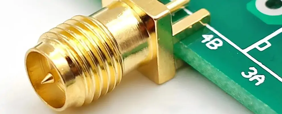
SMA PCB Connector and SMA Connector Straight PCB

A small PCB connector is used when RF signals transition directly onto the board.
Common versions include:
  • Edge mount
  • Through-hole
  • Surface mount
  • sma connector straight pcb
  • End launch designs
The biggest real-world issue is PCB tolerance mismatch.

Real Engineering Pain Point

Many engineers complain that:SMA Female Connector Solder Attachment Thru Hole PCB, but none are with PCB tolerances. The connectors themselves, once mounted, are rough.
This usually happens because:
  • PCB hole spacing is inaccurate
  • Ground pads are uneven
  • Connector flange dimensions are ignored
  • Low-quality machining causes rough alignment

Practical Solution

You should:
  • Match the PCB footprint exactly to the manufacturer’s drawings
  • Control PCB thickness tolerance
  • Use precision-machined connectors
  • Verify solder coplanarity before assembly
NASA connector workmanship standards also stress dimensional inspection and mechanical stability during RF assembly.[3]

SMA Bulkhead Connector and SMA Panel Mount Connector

A small bulkhead connector passes RF signals through an enclosure wall.A small panel mount connector provides stronger mechanical fixation for industrial environments.
Best use cases:
  • Outdoor RF systems
  • Test cabinets
  • Radar housings
  • Communication enclosures
Benefits include:
  • Better grounding
  • Improved shielding
  • Reduced cable stress
  • Easier maintenance

Cable With SMA Connector and RF Pigtail Solutions

A cable with an SMA connector simplifies RF integration.
Common assemblies include:
  • RG316
  • RG174
  • RG58
  • Semi-rigid cable
  • Low-loss microwave cable
Popular custom solutions:
  • RF coaxial connector to SMA
  • RF pigtail cable f to SMA connector
  • sma connector cable assemblies
You should always verify:
  • Impedance consistency
  • Cable loss
  • Bend radius
  • Connector torque
  • Shielding effectiveness

RP SMA vs SMA Connector

What Is the Difference?

The main difference between the RP-SMA and the SMA connectors is the center contact polarity.
TypeCenter Contact
SMA MalePin
RP-SMA MaleSocket
SMA FemaleSocket
RP-SMA FemalePin
RP-SMA is commonly used in WiFi and wireless devices to prevent incompatible antenna connections.
Rosenberger explains that reverse polarity connectors help avoid incorrect RF mating in wireless systems.[4]

SSMA Connectors and Micro SMA Connector Designs

If your RF module becomes smaller, standard SMA may no longer fit.
That is where:
  • ssma connectors
  • micro SMA connector
become useful.
Advantages:
  • Smaller footprint
  • Higher frequency capability
  • Better density for compact microwave modules
Disadvantages:
  • Higher cost
  • Tighter machining tolerance
  • More difficult assembly
SSMA connectors are commonly used in:
  • Aerospace
  • Military systems
  • Phased arrays
  • Compact microwave modules


Can We Use the SMA Connector to Transmit the Clock Signal?

You can use the SMA connector to transmit the clock signal if:
  • The signal path is impedance-controlled
  • Grounding is stable
  • Cable loss is acceptable
  • Connector quality is sufficient
Many RF labs use SMA interfaces for:
  • Reference clocks
  • Timing synchronization
  • High-speed pulse signals
  • Signal generators
The key issue is signal integrity, not simply signal type.

Microwave Connector Vibration Resistance Matters More Than You Think

In radar, drones, vehicles, and outdoor communication systems, microwave connector vibration resistance becomes critical.
Poor connector locking can cause:
  • Phase drift
  • VSWR instability
  • Signal interruption
  • Mechanical fatigue
High-quality SMA connectors normally use:
  • Gold plating
  • Stainless steel shells
  • Precision threading
  • Controlled torque structures
Amphenol RF specifies precise coupling torque ranges to improve vibration stability.[2]

SMA Dimensions and Mechanical Selection

You should always verify SMA dimensions before finalizing PCB layouts.
Important dimensions include:
  • Thread size
  • Pin length
  • Dielectric height
  • Mounting hole spacing
  • Panel thickness
Incorrect SMA plug dimensions often lead to:
  • Poor grounding
  • PCB warpage
  • Connector tilt
  • Difficult cable mating

Real RF Engineering Cases

Case 1 Radar Module Vibration Failure

A radar integrator used low-cost SMA solder connector parts in a vibration-heavy environment.
After 3 months:
  • VSWR increased from 1.2 to 1.8
  • The connector grounding became unstable
  • RF leakage appeared
The issue was solved after switching to stainless steel threaded connectors with better microwave connector vibration resistance.

Case 2 PCB Tolerance Mismatch

A communication module used a generic SMA PCB connector without verifying PCB hole tolerance.
Result:
  • Uneven solder joints
  • Connector tilt
  • Difficult cable mating
After redesigning the PCB footprint using the manufacturer’s mechanical drawings, assembly yield improved by 22%.

Case 3 High Frequency Signal Loss

An engineer used standard SMA above 24 GHz.Insertion loss increased sharply.
Switching to precision SSMA connectors reduced signal loss and stabilized phase consistency.

How to Choose the Right SMA Connector

You should evaluate connectors in this order:

Step 1 Frequency

Check the actual operating frequency.Choose precision SMA or SSMA for high-frequency microwave applications.

Step 2 Mounting Structure

Decide whether you need:
  • sma panel mount connector
  • sma bulkhead connector
  • sma pcb connector
  • cable assembly

Step 3 Mechanical Reliability

Evaluate:
  • Vibration resistance
  • Mating cycles
  • Torque stability
  • Housing material

Step 4 Cable Compatibility

Confirm compatibility with:
  • cable with SMA connector
  • semi-rigid cable
  • low-loss coaxial cable

Conclusion

The right SMA connector is not only about frequency range. You must balance electrical performance, mechanical stability, PCB tolerance, cable structure, and long-term reliability.For RF engineers, the best SMA connections are the ones that remain stable after vibration, repeated assembly, temperature changes, and real production environments.If you choose connectors only by price, you usually pay later in testing, debugging, and field failure.Good RF design starts with stable interconnects.

References

FAQ

1. What does SMA stand for connector?

SMA stands for SubMiniature version A, and you use it for compact RF connector links in testing.

2. What are the disadvantages of SMA connectors?

SMA connectors can add loss, need careful alignment, and may loosen under vibration in your setup.

3. What size wrench for SMA connectors?

You usually use a 5/16 inch wrench to tighten them snugly by hand.

4. CanI use an SMA connector for high power?

SMA suits low-power RF; use N or 7/16 for high power.

5. How do you properly terminate an SMA connector?

You strip, solder or crimp, and keep 50 ohms.

6. How do I choose the right SMA connector?

You match frequency, impedance, size, and mounting style.