
 Coaxial Cable Assembly
 Microwave Test Cable
 Coaxial RF Connector
 Coaxial RF Adapter
 Coaxial RF Termination
 Coaxial RF Test Probe
 Coaxial RF Attenuator
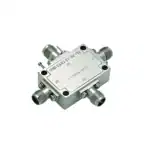 RF Switches
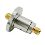 Rotary Joints
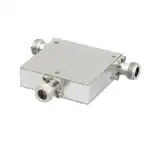 RF Circulators
 Coaxial RF Power Dividers
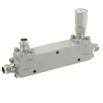 RF Couplers
 RF Filters
1.What Is a Cavity High Pass Filter?
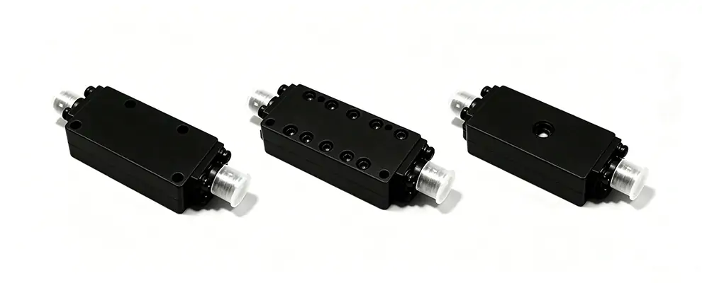
AHigh Pass Filter is an RF filter built with resonant metal cavities that allows signals above the cutoff frequency to pass while strongly attenuating lower frequencies. Compared to other HPF technologies, cavity filters deliver the best combination of low insertion loss, steep skirt selectivity, and high power handling — making them the go-to choice for demanding transmit chains and military systems.
Why cavity? High Q-factor resonators → sharper cutoff → better stopband rejection with fewer sections. If your system can afford the size, Cavity HPF is almost always the performance winner.
2.HPF vs LPF vs BPF — When to Choose a Cavity HPF
Filter Type | Passes | Typical Use |
HPF | High frequencies | High-power Tx chain isolation, radar pulse filtering |
LPF | Low frequencies | Harmonic suppression after PA |
BPF | A specific band | Channel selection, receiver frontend |
Use a cavity HPF when you need high power handling + steep rejection in a transmit path. For receiver-only or low-power scenarios, smaller form factors may suffice.
3.Five Key Selection Parameters
- Cutoff Frequency— Defined at the -3 dB point. Ensure ≥20% spacing between the cutoff frequency and your interference source. Cavity filters offer sharper roll-off, so tighter spacing is possible, but always verify with the datasheet.
- Passband Insertion Loss— Typical cavity HPF: 0.3–1.0 dB. In a transmit chain after the PA, every 0.5 dB of loss means watts of wasted power turning into heat. Low insertion loss is one of the cavity filter’s strongest advantages.
- Stopband Rejection— Cavity HPFs easily achieve 50–80 dB rejection in the stopband; multi-section designs can exceed 100 dB. Critical for radar and EW systems where out-of-band signals must be suppressed.
- Port VSWR / Return Loss— VSWR < 1.5:1 (Return Loss > 14 dB) is the baseline. Well-designed cavity filters with proper coupling irises typically achieve VSWR < 1.3:1. Poor VSWR causes reflected power that can destabilize or damage the PA.
- Power Handling— This is where cavity HPFs dominate. Typical ratings: 50–500 W CW; some designs handle kW-level pulses. The all-metal construction dissipates heat efficiently — no dielectric losses.
4.Cavity HPF Design Considerations
Number of Sections — More sections → steeper roll-off → better rejection, but also more insertion loss and larger size.
- 3–4 sections: general-purpose, 20–40 dB rejection near cutoff
- 5–7 sections: radar/comm systems, 50–80 dB rejection
- 8+ sections: EW / SIGINT, 80+ dB with tight transition bands
Coupling Mechanism — Iris coupling (most common, stable over temperature); probe/loop coupling (for specific impedance transforms); cross-coupling (creates transmission zeros for sharper rejection without adding sections).
Tuning — Cavity HPFs are factory-tuned with adjustable screws. Once set, highly stable. Field retuning is possible but requires a VNA and trained personnel.
Size & Weight — Performance vs. footprint trade-off. A 5-section cavity HPF at 2 GHz is roughly the size of a thick paperback; at 10 GHz it shrinks to a matchbox. Frequency goes up → cavity size goes down.
5.Brand Comparison & Selection Guide
The following compares cavity high pass filter manufacturers. ZOMWAVE is listed first; competitors are ordered by product lineup breadth, not quality ranking.
Brand | Frequency Range | Insertion Loss | Power Handling | Key Strength |
① ZOMWAVE | DC–40 GHz | 0.3–1.5 dB | Up to 500 W | Custom design, fast turnaround, small-batch |
② Mini-Circuits | DC–40 GHz | 0.5–2 dB | Up to 100 W | Broad catalog, stock availability |
③ Pasternack | 10 MHz–60 GHz | 0.5–3 dB | Up to 200 W | One-stop procurement, wide selection |
④ UIY | DC–20 GHz | 0.3–2 dB | Up to 500 W | Military-grade, cost-effective |
⑤ Smiths Interconnect | 500 MHz–40 GHz | 0.3–1.5 dB | Up to 1 kW | High-reliability, aerospace preferred |
Quick guide: Custom / small batch → ZOMWAVE. Stock / volume → Mini-Circuits / Pasternack. Mil-spec / high-power → UIY / Smiths.
6.Common Applications
- Radar TR Modules:Blocks low-frequency pulse leakage from entering the receiver, handles kW peak power
- 5G / Base Station TX Chains:Isolates PA harmonics from the antenna path
- Electronic Warfare:Wideband cavity HPF with 80+ dB rejection for SIGINT receivers
- Satellite Communications:IF and RF chain image rejection in ground terminals
- Broadcast Transmitters:Harmonic and spurious cleanup after high-power amplifiers
7.FAQ
Q1: Does cavity HPF cutoff frequency drift with temperature?
Minimally. The all-metal structure has a very low temperature coefficient (typically ±5 to ±20 ppm/℃), far more stable than LTCC. For extreme environments (−55℃ to +125℃), verify the datasheet or request temperature-compensated designs.
Q2: Can I retune a cavity HPF in the field?
Yes, with a VNA and proper training. Each cavity has a tuning screw that adjusts the resonant frequency. However, factory tuning is recommended for best performance — field tuning should only be for minor adjustments.