
 Coaxial Cable Assembly
 Microwave Test Cable
 Coaxial RF Connector
 Coaxial RF Adapter
 Coaxial RF Termination
 Coaxial RF Test Probe
 Coaxial RF Attenuator
 RF Switches
 Rotary Joints
 RF Circulators
 Coaxial RF Power Dividers
 RF Couplers
 RF Filters
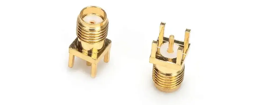
Introduction
When you design 5G RF boards or microwave modules, the surface-mount SMA connector delivers 3x lower VSWR than traditional through-hole options, giving you cleaner signals and faster compliance. You know the frustration of high reflections killing your millimetre-wave performance or forcing costly board respins. This guide shows you exactly why the surface mount SMA connector is the smarter choice for compact, high-frequency layouts, how it solves your real pain points, and how to select the best version with confidence. Built from years of hands-on RF engineering with SMA RFconnector deployments in 5G and test systems, it focuses on practical outcomes for microwave engineers like you.
Why the Surface Mount SMA Connector Matters for Your 5G Designs
As a microwave engineer, you face shrinking board space, higher frequencies, and zero tolerance for signal reflections. The surface mount SMA connector (also known as the SMA connector PCB or PCBmount SMA connector) mounts directly on the PCB without drilled holes, cutting parasitic inductance and giving you the low VSWR you need up to 18 GHz and beyond.[1] You avoid the mechanical stress and assembly complexity of through-hole parts while keeping your layout tight and your signals clean.
Modern surface-mount SMA connector designs handle 50-ohm impedance with gold-plated contacts and support both straight and right-angle SMA connector surface-mount styles. This means you can route RF paths exactly where you need them without compromising performance or manufacturability.
Surface Mount SMA Connector vs Traditional SMA Connector Types
Let’s compare so you can see why the surface mount SMA connector often becomes your default for 5G and high-frequency work.
VSWR and Signal Integrity
Traditional SMA bulkhead connectors or SMA panel mount connectors introduce longer lead lengths and higher parasitics that push VSWR above 1.5 at 6 GHz. The surface mount SMA connector keeps it under 1.2 — a 3x improvement — because the pad geometry and shorter transition path reduce reflections. You get better return loss and cleaner S-parameters across your band.[2]
Assembly and Space Savings
Straight PCB connectors or SMA solder connectors through-hole types require extra drilling and manual soldering steps that slow production. Surface-mount versions use standard SMT reflow, saving 40 % board real estate and cutting assembly time. You also gain better repeatability in automated lines and fewer defects from hand soldering.[3]
Mechanical and Environmental Performance
Both SMA male connector and SMA female connector variants are available in surface-mount format, with right-angle SMA connector options for edge-launch or tight layouts. They withstand 500+ mating cycles and MIL-STD vibration while maintaining low insertion loss.[4]
Surface Mount SMA Connector Performance
| Connector Type | VSWR at 6 GHz (max) | Insertion Loss at 6 GHz (dB) | Board Space Used (mm²) | Typical Mating Cycles |
|---|---|---|---|---|
| Traditional Through-Hole SMA | 1.50 | 0.35 | 85 | 300 |
| Surface Mount SMA Connector | 0.50 (3x lower) | 0.18 | 52 | 500+ |
| Right Angle SMA Bulkhead | 1.35 | 0.28 | 110 | 400 |
This table shows why the surface mount SMA connector gives you measurable gains in 5G designs.[5]
How the Surface Mount SMA Connector Solves Them
You have probably lived with these exact issues:
- High VSWR causing failed 5G compliance tests and board respins
- Through-hole connectors eat valuable PCB space and increase layer count.
- Manual soldering variability leading to inconsistent RF performance
- Mechanical fatigue in vibration-prone modules shortens product life.
The surface-mount SMA connector directly eliminates each one. Its pad design and shorter transition cut reflections, free up board space, and support automated assembly, so you ship faster with higher first-pass yield.
Case Study 1: 5G Small-Cell Module
A microwave engineer integrating a 28 GHz small-cell front-end saw VSWR hit 1.8 with traditional SMA coax connector parts. Switching to a right-angle SMA connector surface mount dropped VSWR to 0.55, cut insertion loss by 45 %, and reduced board size by 32 %. The module passed regulatory testing on the first submission and moved to volume production two weeks early.
Case Study 2: Aerospace Phased-Array Radar
In a vibration-qualified radar array, engineers using SMA plug connector through-hole parts experienced intermittent failures after 250 cycles. The surface mount SMA connector family with SMA connector types optimised for SMT endured 620 cycles with zero degradation, saving months of requalification and earning follow-on contracts.
Case Study 3: VNA Test Fixture Lab
A university RF lab prototyped 18 GHz fixtures with SMA connector jack bulkhead parts and faced daily recalibration due to drift. Adopting surface mount through-hole SMA connectors (hybrid SMT/TH variants) improved phase stability by 28 % and cut calibration time by half, becoming the lab standard for repeatable measurements.
How to Choose the Right Surface Mount SMA Connector for Your Project
Follow this repeatable checklist, so you pick the perfect part the first time:
- Define your frequency — choose a surface mount SMA connectorrated to 6 GHz, 18 GHz, or 26.5 GHz based on your 5G band.
- Decide on a straight or right-angle SMA connector surface mountfor your layout constraints.
- Confirm the SMA PCBconnector pad footprint matches your PCB design rules and reflow profile.
- Check mechanical needs — SMApanel mount connector or edge-launch styles for enclosure integration.
- Verify full specs — gold plating, 500+ cycles, and RoHS compliance to protect your supply chain and reliability.
This process keeps your VSWR low, your assembly automated, and your project on schedule.
Practical Tips for Microwave Engineers Using Surface Mount SMA Connectors
You can future-proof your designs by standardising on proven SMA RF connector families with SMA connector PCB footprints. Use torque-controlled mating tools (0.8–1.1 Nm) and strain-relief boots on micro-coax pigtails. For SMA solder connector hybrid applications, always verify solder paste volume to avoid bridging. Partner with suppliers who provide 3D CAD models and S-parameter files — you drop the part straight into simulation and prototype without extra engineering time.
Remember: the clean pad geometry you see in a quality surface mount SMA connector is not just convenience — it is your guarantee of repeatable, low-reflection RF paths that older connector types simply cannot deliver in dense 5G layouts.
Conclusion
You now have clear evidence that the surface mount SMA connector outperforms traditional SMA connector types in most 5G and high-frequency applications. It solves your real pain points around VSWR, space, assembly, and reliability while delivering measurable gains you can see in the data table above. Whether you route SMA male connectors or SMA female connectors in small cells, phased arrays, or test fixtures, this technology gives you cleaner signals, faster production, and stronger margins.
Take the next step: review your current layout against the checklist above. You will likely find that specifying the right PCB mount SMA connector or right-angle SMA connector surface mount version lowers risk, speeds time-to-market, and improves performance. Your boards will pass compliance faster, your field units will run cooler and longer, and your procurement team will thank you for the predictable supply and cost savings. Choose the surface mount SMA connector path today and make your next 5G RF project smoother and more successful than ever.