
 Coaxial Cable Assembly
 Microwave Test Cable
 Coaxial RF Connector
 Coaxial RF Adapter
 Coaxial RF Termination
 Coaxial RF Test Probe
 Coaxial RF Attenuator
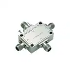 RF Switches
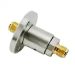 Rotary Joints
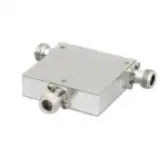 RF Circulators
 Coaxial RF Power Dividers
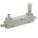 RF Couplers
 RF Filters
Introduction
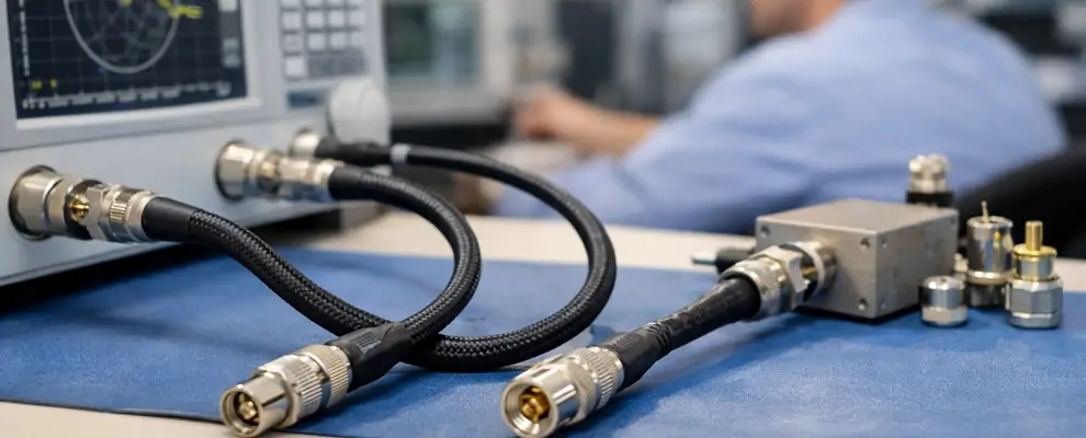
A VNA test cable is a critical connection component used between a vector network analyzer (VNA) and the device under test. Although VNAs provide highly accurate measurement capability, the cable connecting the instrument and DUT can directly affect measurement stability, repeatability, and calibration results.
For RF engineers, test laboratories, and system integrators, selecting the right cable is not only about frequency range. You also need to consider phase stability, insertion loss, connector compatibility, mechanical durability, and field conditions. The right solution helps you reduce measurement uncertainty, shorten debugging time, and improve confidence in RF validation.
Why VNA Test Cables Matter for Accurate RF Measurements
The Hidden Impact of Cable Performance on Measurement Results
When you perform RF measurements, you may focus on the accuracy of the VNA itself, but the connection path between the instrument and your device is equally important. A high-quality VNA system can still produce unstable results if the cable introduces excessive loss, phase variation, or unwanted reflections.
A VNA test cable provides the electrical link between the analyzer port and the DUT. During measurements such as S-parameter testing, antenna characterization, filter verification, and RF component validation, cable performance directly influences measurement repeatability.
According to the National Institute of Standards and Technology (NIST), accurate RF measurements require proper calibration procedures and control of measurement uncertainty sources, including connection interfaces and test setups.[1]
For example, when testing a high-frequency filter, a small phase change caused by cable movement can shift measurement results. This becomes more noticeable in applications above 20 GHz, where mechanical stability and phase consistency become critical.
What Is a VNA Test Cable?
A VNA test cable is a precision RF cable assembly designed specifically for vector network analyzer measurements. Unlike standard RF cables, these cables are optimized for low insertion loss, stable phase performance, controlled impedance, and repeated connection cycles.
You typically use VNA cables in applications such as:
- RF component characterization
- Antenna testing
- 5G module validation
- Microwave device measurement
- Semiconductor RF testing
- Laboratory calibration systems
Most professional solutions use 50-ohm impedance because modern RF measurement equipment and components are generally designed around a 50-ohm system.
The main purpose of a VNA cable is not only to transfer signals but also to maintain measurement accuracy throughout repeated testing operations.
How VNA Test Cable Assemblies Support Reliable Testing
VNA test cable assemblies combine RF cables with precision connectors designed for specific measurement environments. A complete assembly normally includes:
- Low-loss coaxial cable
- Precision RF connectors
- Strain relief structures
- Phase-stable cable design
- Protective outer jacket
Compared with standard RF cables, professional test assemblies provide better mechanical stability and electrical consistency.
When you select VNA cables, you should evaluate more than frequency capability. Cable movement, bending radius, connector wear, and temperature variation can all influence measurement results.
Key Specifications You Should Evaluate Before Purchasing
Choosing a suitable cable requires understanding the specifications that affect your testing environment.
Frequency Range and 67 GHz VNA Test Cables
Frequency capability is one of the first specifications you should confirm.
For example:
- Low-frequency RF testing may require cables below 6 GHz.
- 5G and microwave applications often require higher-frequency solutions.
- Advanced mmWave measurement systems may require 67 GHz VNA test cables.
At higher frequencies, signal loss increases and mechanical tolerances become more important. A cable designed for 6 GHz testing may not provide stable performance in a 67 GHz measurement environment.
Phase Stability, Insertion Loss, and Return Loss
For accurate measurements, you need stable electrical performance.
Important parameters include:
| Parameter | Why It Matters |
| Insertion Loss | Determines signal attenuation through the cable |
| Return Loss | Indicates signal reflection caused by impedance mismatch |
| Phase Stability | Maintains measurement consistency during movement |
| VSWR | Shows quality of impedance matching |
According to Keysight Technologies’ VNA measurement guidance, calibration quality and measurement accuracy depend on controlling errors throughout the entire RF measurement path, including cables and connectors.[2]
Connector Compatibility and Adapter Options
A common challenge during RF testing is matching different equipment interfaces.
Modern test environments may use:
- 2.92 mm connectors
- 3.5 mm connectors
- SMA connectors
- Type-N connectors
- SMP and SMPM interfaces
In these cases, VNA test port cables and adapter solutions allow engineers to connect different measurement platforms while maintaining RF performance.
For applications requiring additional reach, VNA test port extension cables provide more flexibility by extending the connection distance between the VNA and the DUT without redesigning the entire test setup.
VNA Cable Types and Performance Comparison
Different testing environments require different cable characteristics. The following comparison helps you select a suitable solution.
| Cable Type | Typical Frequency Range | Main Application | Key Advantage |
| Standard RF Cable | DC-6 GHz | General RF connection | Cost-effective signal connection |
| Laboratory VNA Cable | DC-18 GHz | RF component testing | Better phase stability and repeatability |
| High Frequency VNA Cable | DC-40 GHz | Microwave measurement | Lower loss at high frequencies |
| 67 GHz VNA Test Cable | DC-67 GHz | Advanced mmWave testing | High-frequency measurement capability |
| VNA Test Port Extension Cable | Application dependent | Extended test setups | Improved accessibility and flexibility |
Selecting the correct cable type depends on your measurement frequency, accuracy requirements, connector interface, and operating environment.
Common Engineering Problems and How the Right Cable Solves Them
Problem 1: Calibration Drift During RF Testing
One of the most common challenges you face during VNA measurements is calibration drift. Even after a proper calibration process, measurement results may change if the cable position, connector condition, or environmental conditions are unstable.
For example, during antenna testing, engineers often need to move the test cable to access different measurement positions. If the cable has poor phase stability, the measured S-parameters may shift, creating uncertainty during product verification.
A stable VNA test cable assembly helps reduce this problem through:
- Improved phase repeatability
- Strong mechanical structure
- Low insertion loss variation
- Reliable connector performance
According to NIST measurement practices, controlling measurement uncertainty requires attention to every element in the measurement chain, including cables, connectors, and calibration standards.[1]
A practical example is a wireless module manufacturer validating a new antenna design. When the same DUT is measured multiple times, unstable cables may create different results, causing engineers to repeat tests unnecessarily. Using phase-stable VNA cables improves confidence in the final measurement data.
Problem 2: Limited Access to VNA Test Ports
In many RF laboratories, the DUT location is not always close to the VNA equipment. Large test fixtures, shielding chambers, and automated test systems often require additional cable distance.
A short cable may create installation limitations, while an incorrect extension solution may introduce excessive signal loss.
This is where VNA test port extension cables become useful.
They help you:
- Reach difficult DUT positions.
- Improve test fixture flexibility.
- Reduce mechanical stress on VNA ports.
- Simplify system integration
For example, in a production test environment, multiple RF modules may require different fixture locations. Instead of moving the VNA repeatedly, engineers can use properly selected extension cables to create a more efficient testing workflow.
Problem 3: Signal Loss in High-Frequency Applications
As operating frequency increases, cable performance becomes more challenging. Higher frequencies require tighter manufacturing control because even small imperfections can affect signal quality.
This is especially important for:
- 5G mmWave testing
- Satellite communication components
- Radar systems
- High-speed RF modules
For these applications, 67 GHz VNA test cables provide the bandwidth capability required for advanced measurements.
A typical comparison:
| Frequency Application | Recommended Cable Solution | Main Requirement |
| Below 6 GHz wireless testing | Standard RF test cables | Reliable connection and low cost |
| 6-18 GHz RF components | Laboratory VNA cables | Improved phase stability |
| 18-40 GHz microwave testing | High-frequency VNA cables | Lower insertion loss |
| 40-67 GHz mmWave testing | 67 GHz VNA test cables | Maximum frequency stability |
How to Select the Right VNA Test Cable Solution
Selecting a cable solution requires more than choosing the highest frequency option. You should match the cable characteristics with your actual testing requirements.
Step 1: Confirm Frequency and Measurement Requirements
Before purchasing, identify:
- Maximum operating frequency
- Required measurement accuracy
- Signal bandwidth
- Test environment
For example:
If you only test Wi-Fi modules below 6 GHz, a 67 GHz solution may provide unnecessary cost. However, if you validate mmWave devices, selecting a lower-frequency cable may create measurement limitations.
Step 2: Match Connectors and Test Port Interfaces
Connector compatibility is another important consideration.
You should confirm:
- VNA port connector type
- DUT connector type
- Required adapters
- Mating cycle requirements
Common connector options include:
| Connector Type | Typical Frequency Capability | Application |
| SMA | Up to approximately 18 GHz | General RF testing |
| 3.5 mm | Up to 26.5 GHz | Precision RF measurement |
| 2.92 mm | Up to 40 GHz | High-frequency testing |
| 1.85 mm | Up to 67 GHz | mmWave applications |
Connector selection directly affects repeatability, calibration accuracy, and long-term reliability.
Step 3: Consider Environment and Service Life
Your operating environment determines the required cable construction.
You should consider:
- Laboratory or field use
- Cable movement frequency
- Temperature changes
- Required bending flexibility
- Connector durability
A cable used daily in a laboratory requires different mechanical performance compared with a cable installed permanently inside a test fixture.
Real Application Examples
Example 1: 5G RF Module Verification
A communication equipment manufacturer needed to validate new 5G RF modules during development. The main challenge was inconsistent measurement results between different test cycles.
The engineering team identified that cable movement and connector repeatability affected the measurement process.
Solution:
They upgraded to phase-stable VNA test port cables with improved mechanical stability.
Results:
| Before Improvement | After Improvement |
| Repeated calibration required frequently | More stable measurement process |
| Higher test variation | Improved repeatability |
| Longer debugging cycles | Faster RF validation |
This type of improvement helps engineering teams reduce unnecessary testing time during product development.
Example 2: Aerospace Communication Testing
Aerospace RF systems often require highly reliable testing because equipment may operate in demanding environments.
During satellite communication component testing, engineers must evaluate:
- Low signal loss
- Stable phase response
- Reliable connectors
Aerospace testing commonly uses precision RF measurement systems because small signal changes can influence system evaluation.
IEEE microwave measurement research highlights the importance of accurate calibration and stable measurement setups for high-frequency characterization.[4]
For these applications, selecting suitable VNA test cable assemblies helps maintain consistent measurement conditions.
Example 3: Semiconductor and Microwave Device Testing
Semiconductor manufacturers frequently test RF devices at high frequencies. These tests require accurate characterization of:
- Filters
- Amplifiers
- Oscillators
- RF integrated circuits
A common challenge is limited test access because semiconductor fixtures are often compact.
Using flexible VNA test port extension cables allows engineers to connect measurement equipment while maintaining fixture accessibility.
The correct cable solution improves:
- Test repeatability
- Equipment protection
- Production efficiency
Procurement Checklist for VNA Test Cable Assemblies
Before purchasing, you should confirm the following specifications:
| Selection Item | What You Should Confirm |
| Frequency Range | Maximum operating frequency and bandwidth requirement |
| Impedance | 50-ohm RF system compatibility |
| Connector Type | SMA, 3.5 mm, 2.92 mm, 1.85 mm, or custom options |
| Phase Stability | Required measurement repeatability |
| Insertion Loss | Maximum acceptable signal attenuation |
| Cable Length | Required test setup distance |
| Mechanical Requirements | Flexibility, bending cycles, and durability |
| Certification | Quality control and manufacturing documentation |
A reliable supplier should provide technical specifications, inspection data, and customization support when standard products cannot meet your test requirements.
Conclusion
Choosing the right VNA test cable is an important step in building a reliable RF measurement system. The cable between your VNA and DUT directly influences signal accuracy, calibration stability, and testing efficiency.
Whether you need standard laboratory cables, customized VNA test cable assemblies, high-frequency solutions such as 67 GHz VNA test cables, or flexible VNA test port extension cables, the correct selection depends on your frequency range, connector requirements, and application environment.
A well-designed cable solution helps you reduce measurement uncertainty, avoid repeated testing, and achieve more reliable RF validation results.
References
[1] National Institute of Standards and Technology (NIST), RF Measurement and Calibration Resources
[2] Keysight Technologies, Vector Network Analyzer Measurement and Calibration Fundamentals
[3] Rohde & Schwarz, Vector Network Analyzer Applications and RF Measurement Solutions
[4] IEEE Xplore Digital Library, Microwave and RF Measurement Research Publications
FAQ
1. How do you choose the right VNA test cable for 67 GHz measurements?
A 67 GHz solution is suitable for mmWave testing where high bandwidth and phase stability are required. You should evaluate connector type, insertion loss, return loss, and mechanical stability before selection. Proper 67 GHz VNA test cables help maintain measurement accuracy in advanced RF applications.
2. What is the difference between standard RF cables and VNA test cable assemblies?
Standard RF cables are designed for general signal transmission, while VNA test cable assemblies are optimized for measurement accuracy. They typically provide better phase stability, lower loss variation, and improved connector repeatability for laboratory testing.
3. When should you use VNA test port extension cables?
You should use VNA test port extension cables when your DUT or fixture cannot be positioned close to the VNA ports. They provide additional installation flexibility while maintaining RF measurement performance when properly selected and calibrated.
4. How often should VNA cables be replaced in laboratory environments?
Replacement depends on usage frequency, bending cycles, connector condition, and measurement requirements. Regular inspection is recommended because damaged cables may increase insertion loss, reflection, and measurement uncertainty.
5. Can customized VNA test port cables improve measurement accuracy?
Yes. Customized VNA test port cables can match specific connector interfaces, lengths, frequency ranges, and mechanical requirements. This helps optimize test setups and reduce compatibility issues in specialized RF applications.