
 Coaxial Cable Assembly
 Microwave Test Cable
 Coaxial RF Connector
 Coaxial RF Adapter
 Coaxial RF Termination
 Coaxial RF Test Probe
 Coaxial RF Attenuator
 RF Switches
 Rotary Joints
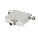 RF Circulators
 Coaxial RF Power Dividers
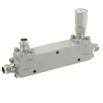 RF Couplers
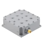 RF Filters
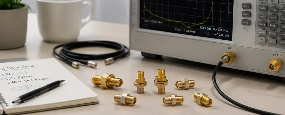
Introduction
When you work with RF test racks, the sma to sma adapter is not a small accessory—it is part of your signal integrity chain. In the first 100 words, you already rely on sma to sma adapter choices to decide whether your system behaves like a controlled 50 Ω environment or a noisy, reflection-heavy setup.For system integrators, lab engineers, and procurement teams, this decision affects calibration accuracy, downtime, and even long-term test repeatability. In this guide, you will see how sma to sma adapter selection impacts VSWR, mechanical stability, and connector compatibility in real test environments.
Why SMA to SMA Adapter Selection Matters in Test Racks
When you design or maintain RF test systems, you are not just connecting cables—you are controlling reflections, insertion loss, and impedance continuity.
A poor choice of sma to sma adapter can introduce:
- Unstable VSWR above 1.5
- Repeatability drift in multi-cycle testing
- Mechanical stress on PCB or front-panel ports
According to RF connector fundamentals, SMA interfaces are designed for 50 Ω operation up to microwave frequencies when properly matched [1]. However, real-world mismatch often comes from adapter stacking, not the connector itself.
You need to treat every adapter as a measurable RF component.
Key SMA to SMA Adapter Types You Will Use
In test racks and RF benches, you typically deal with multiple structural variants. Each one affects signal integrity differently.
Common SMA Adapter Variants
- sma female to female adapter
- sma female to sma female bulkhead adapter
- sma bulkhead adapter
- sma to sma bulkhead adapter
- sma female bulkhead adapter
- sma male to sma female adapter
- sma to rp sma adapter
Each variant changes mechanical grounding, shielding continuity, and panel stability.
Electrical Performance Comparison (Real Engineering View)
Below is a practical comparison based on typical RF lab conditions.
| Adapter Type | Typical VSWR | Insertion Loss (DC–6 GHz) | Best Use Case |
| sma female to female adapter | 1.10–1.25 | 0.1–0.3 dB | Cable extension |
| sma bulkhead adapter | 1.05–1.20 | 0.05–0.2 dB | Panel feedthrough |
| sma male to sma female adapter | 1.15–1.30 | 0.1–0.4 dB | Interface conversion |
| sma to rp sma adapter | 1.20–1.50 | 0.2–0.5 dB | WiFi / antenna bridging |
These values align with typical coaxial connector behavior described in RF transmission line theory.
Mechanical Stability vs RF Performance Trade-off
You often underestimate mechanical design. But in real test racks, vibration, torque, and mating cycles matter as much as RF specs.
For example:
- Bulkhead SMA designs reduce PCB stress
- Female-to-female inline adapters increase stack loss risk
- RP-SMA mismatches introduce accidental impedance discontinuities
Connector standards such as SMA geometry are defined in RF connector specifications to ensure repeatability.
How You Should Choose the Right SMA to SMA Adapter
You should not select based on price alone. You should evaluate:
Selection Checklist
- Frequency range (DC–6 GHz or up to 18 GHz)
- VSWR stability (<1.3 preferred for test racks)
- Mechanical mounting (bulkhead vs inline)
- Gold plating thickness (corrosion resistance)
- Mating cycle rating (>500 cycles for lab use)
Industry suppliers such as TE Connectivity and Amphenol RF specify these parameters for lab-grade connectors .
Real Use Cases in RF Test Environments
Case 1: Calibration Bench Instability
A lab using stacked female-to-female adapters saw ±0.4 dB drift due to cumulative mismatch.
Case 2: 5G Module Testing
Bulkhead SMA adapters improved repeatability by stabilizing reference grounding.
Case 3: Antenna Characterization
Using SMA to RP-SMA adapters caused measurable return loss increase above 2.4 GHz.
These behaviors align with coaxial transmission principles in RF engineering documentation [2].
Why Low VSWR Matters More Than You Think
Low VSWR is not just a specification—it directly affects measurement trust.
A shift from 1.2 to 1.5 VSWR can:
- Increase reflected power by ~4%
- Distort S-parameters in vector network analysis
- Reduce calibration accuracy in automated test systems
Conclusion
When you select an sma to sma adapter, you are not buying a passive connector—you are defining your RF system’s stability boundary.
If your work involves test racks, calibration benches, or high-frequency RF validation, choosing the correct SMA adapter type ensures your results stay repeatable, traceable, and engineering-grade.
References
[2] Keysight Technologies – RF Network Analysis Fundamentals
FAQ
1. What VSWR should I expect from an sma to sma adapter?
Typical RF-grade sma to sma adapter provides VSWR between 1.10–1.30 from DC to 6 GHz depending on structure and plating quality.
2. When should I use a sma bulkhead adapter instead of inline?
Use sma bulkhead adapter when you need chassis grounding and mechanical strain relief in test racks or panel-mounted RF systems.
3. Does stacking sma female to female adapter affect signal loss?
Yes. Multiple sma female to female adapter stacking increases insertion loss and can raise return loss above acceptable test limits.
4. Is sma to rp sma adapter suitable for precision RF testing?
No. sma to rp sma adapter introduces impedance mismatch risk and is not recommended for calibrated RF measurement systems.
5. What is the main difference between sma male to sma female adapter types?
The sma male to sma female adapter mainly differs in mechanical orientation, but RF performance depends on precision machining and VSWR control.