
 Coaxial Cable Assembly
 Microwave Test Cable
 Coaxial RF Connector
 Coaxial RF Adapter
 Coaxial RF Termination
 Coaxial RF Test Probe
 Coaxial RF Attenuator
 RF Switches
 Rotary Joints
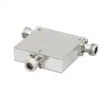 RF Circulators
 Coaxial RF Power Dividers
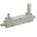 RF Couplers
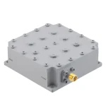 RF Filters
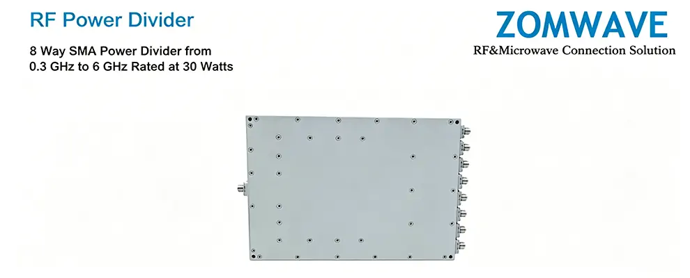
When you drop a power divider symbol on the schematic, the first question isn’t “how much insertion loss?” — it’s “how many ways do I actually need?” This article cuts through the specs to give you 4 decision dimensions that actually determine whether your system works or fails in production.
TL;DR: If you don’t have a hard requirement for 8 ways, go with 2-way or 4-way. Better insertion loss, phase consistency, power handling, and easier to debug in the lab. Browse ZOMWAVE coaxial RF power dividers for your specific configuration.
1. Insertion Loss: The Theoretical Number Is Just the Starting Point
Distribution loss in a power divider is physics — there’s no workaround. The theoretical loss follows the formula 10×log₁₀(N), where N is the number of output ports. But that’s only the distribution loss. Real-world performance adds parasitic losses on top.
Port Config | Theoretical Loss | Typical Extra Loss* | Total System Loss |
2-Way | 3.0 dB | 0.2–0.5 dB | 3.2–3.5 dB |
4-Way | 6.0 dB | 0.3–0.7 dB | 6.3–6.7 dB |
8-Way | 9.0 dB | 0.5–1.0 dB | 9.5–10.0 dB |
*Extra loss comes from: Wilkinson isolation resistor parasitic resistance/inductance, PCB microstrip trace loss, and connector frequency response (especially for SMA/N at 18+ GHz).
Where it bites you:
- If your link budget margin is ≤ 3 dB → you can only use 2-way. Full stop.
- If transmit power is ≥ 30 dBm → 4-way and 8-way become viable, but you must verify the end-of-chain power meets receiver sensitivity requirements.
- For wideband applications (2–18 GHz) → request VNA-measured S21 curves, not just the datasheet typical value. Connector transitions dominate loss at the band edges.
ZOMWAVE reference: 2-way Wilkinson power dividers (SMA, DC-18 GHz) deliver 3.2–3.5 dB total loss typically. 4-way units in the same series run 6.3–6.7 dB total. Compare both on the coaxial power divider category page.
2. Amplitude and Phase Consistency: More Ports Mean More Calibration Pain
Output port amplitude imbalance and phase offset directly determine your system’s beamforming accuracy in phased arrays, or channel matching in MIMO. This is where 8-way designs really hurt.
Metric | 2-Way | 4-Way | 8-Way |
Amplitude match (typical) | ±0.1 dB | ±0.2 dB | ±0.3 dB |
Phase match (typical) | ±1° | ±2° | ±3–5° |
Calibration effort | Easy (single cal kit) | Medium (TRL cal kit needed) | Hard (ECal required) |
Why 8-way consistency is hard:
- PCB trace symmetry: All 8 output paths must have identical electrical length. Any asymmetry from layout drift, solder paste variation, or via placement directly converts to phase error.
- Isolation resistor tolerance: 8-way requires 7 isolation resistors. In a Wilkinson, each resistor’s value error compounds. 1% tolerance on 7 resistors = potentially 7× the mismatch of a 2-way design with 1 resistor.
- Connector repeatability: All 8 SMA/N connectors must be from the same manufacturing batch. VSWR differences between ports from different lots are common and hard to track down.
Bottom line: If your system requires phased array beamforming or active antenna MIMO, amplitude/phase consistency is a hard requirement. Use 2-way or 4-way. If you’re just splitting power to feed antennas in a simple feed network, 8-way is acceptable — phase error doesn’t matter there.
3. Power Capacity: It Doesn’t Scale Linearly — It Falls Off a Cliff
The power capacity of a power divider is not simply “rated power divided by number of ways.” Isolation resistors dissipate power in a Wilkinson design, and the frequency-dependent dielectric breakdown strength of the substrate causes dramatic derating at millimeter-wave frequencies.
Port Config | Rated Power (CW) | Usable Power (typical)* | 2.92mm (18–40 GHz) |
2-Way | 30 W | 25–28 W | 10 W (derated to 3 W at 40 GHz) |
4-Way | 30 W | 20–25 W | 8 W (derated to 2 W at 40 GHz) |
8-Way | 30 W | 15–20 W | Not recommended |
*Usable power = rated power minus isolation resistor dissipation, frequency derating, and thermal derating. For example, a 30 W 4-way Wilkinson at 18 GHz might deliver only 20 W total across all 4 ports — not 7.5 W per port.
Frequency derating curve:
- DC–6 GHz: Full rated power available (no derating)
- 6–18 GHz: Derate to 70–80% of rated power
- 18–40 GHz (2.92mm connectors): Derate to 30–40% — this is where 8-way designs become impractical
Field advice: For Ka-band applications (27–40 GHz), 8-way is effectively not an option. The power per port after derating is too low for most active antenna systems. Use 2-way instead, then cascade if you need more ports. See ZOMWAVE 2-way units for Ka-band options.
4. Cost and Size: The Hidden System-Level Expenses
The power divider’s unit price is the visible cost. The real system cost lives in board area, assembly labor, and failure mode analysis.
Port Config | Typical Size (SMA, Wilkinson) | Unit Price (ref.) | System Cost Impact |
2-Way | 25 × 30 mm | $80–120 | Minimal. Easy PCB placement, short traces. |
4-Way | 40 × 50 mm | $150–250 | Moderate. Symmetric trace routing required. |
8-Way | 60 × 80 mm | $300–500 | High. Large footprint, complex routing, assembly time ×4 vs 2-way. |
Hidden costs that add up:
- Calibration labor: An 8-way power divider needs all 8 ports measured with a VNA. At 5 min/port = 40 min bench time. A 2-way needs 10 min. That’s 30 extra minutes per unit in production test.
- Failure mode severity: If 1 port fails in an 8-way module, you replace the entire divider. In a 2-way design, you can desolder and replace just the failed unit.
- Inventory complexity: 8-way models (SMA/N/2.92mm × frequency variants) multiply your SKUs. Each SKU needs safety stock, which ties up working capital.
Decision rule: Small-batch prototypes or one-offs: 8-way is acceptable — fewer component SKUs, faster assembly. High-volume production: 2-way or 4-way wins on serviceability and inventory flexibility. Browse 4-way options for mid-range port counts.
Selection Decision Tree
Start here:
- Is your link budget margin ≤ 3 dB? → Yes → 2-way only. End of decision.
- Does your system require phased array beamforming or active antenna MIMO? → Yes → 2-way or 4-way only.
- Operating frequency ≥ 18 GHz (Ka/V-band)? → Yes → Avoid 8-way. Use 2-way (cascade if needed).
- Production volume high (>100 units/year)? → Yes → 2-way or 4-way. Lower failure cost, simpler inventory. → No → 8-way acceptable for BOM simplification.
Summary: 4-Dimension Quick Reference
Dimension | Favors 2-Way | Favors 4-Way | Favors 8-Way |
Insertion Loss | Best (3.2–3.5 dB) | Moderate (6.3–6.7 dB) | Worst (9.5–10 dB) |
Amplitude/Phase | Best (±0.1 dB, ±1°) | Good (±0.2 dB, ±2°) | Challenging (±0.3 dB, ±3–5°) |
Power Handling | Best (25–28 W usable) | Good (20–25 W usable) | Poor at 18+ GHz |
Cost/Size | Smallest, cheapest, easiest to repair | Balanced | Largest, highest unit cost, hardest to service |
The short version: Unless your system mandates 8 ways for an 8-element active array, default to 2-way or 4-way. Better loss, better phase, better power, and simpler to debug, build, and service. Explore ZOMWAVE coaxial RF power dividers to find the exact configuration for your application.