
 Coaxial Cable Assembly
 Microwave Test Cable
 Coaxial RF Connector
 Coaxial RF Adapter
 Coaxial RF Termination
 Coaxial RF Test Probe
 Coaxial RF Attenuator
 RF Switches
 Rotary Joints
 RF Circulators
 Coaxial RF Power Dividers
 RF Couplers
 RF Filters
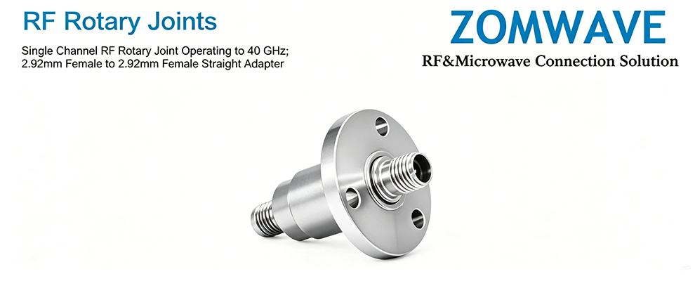
Introduction
A radar antenna needs to rotate 360 degrees continuously. But the RF signal has to travel from that rotating antenna to a stationary transceiver. Bridging that gap — rotating while transmitting RF — is exactly what an RF rotary joint does.
You will find these components in radar systems, satellite communications terminals, MRI scanners, and industrial automation equipment. Any application where a rotating part needs to exchange RF signals with a fixed system needs a rotary joint. This article breaks down how they work, the two main design approaches, and the five parameters that matter most when selecting one.
What Is an RF Rotary Joint
An RF rotary joint is a precision coaxial rotating connector designed to transmit radio frequency signals across a mechanical rotation boundary without degrading signal integrity. The core engineering challenge: insertion loss and VSWR must remain stable as the joint rotates. A radar system cannot afford sudden VSWR spikes mid-rotation — that means missed or distorted target returns.
Basic anatomy:
- Rotor: attached to the rotating side.
- Stator: attached to the stationary side.
- Contact mechanism: the critical design element that determines performance limits.
Contact vs. Non-Contact: A Technical Comparison
Parameter | Contact Type (capacitive/brush) | Non-Contact Type (near-field coupling) |
Insertion loss | Low (0.2–0.5 dB) | Higher (1.0–2.0 dB) |
VSWR | Excellent (1.2:1–1.3:1) | Moderate (1.5:1–2.0:1) |
Rotational life | Finite (1M–10M cycles) | Essentially unlimited |
Best for | Lower frequencies, high stability needs | mmWave, ultra-long life requirements |
Cost | Lower | Higher |
Engineering note: For radar and satcom applications, contact-type rotary joints typically deliver the best balance of RF performance and cost. Non-contact designs are worth considering when the application demands million-plus rotation cycles without maintenance.
Five Key Selection Parameters
1. Frequency Range
Match the joint to your system operating band. Wider is not always better — an overly broad frequency range often means degraded VSWR at specific frequencies within the range.
Bandwidth | Frequency Range | Typical Use |
Narrowband | DC–3 GHz | VHF/UHF applications |
Mid-band | DC–18 GHz | Covers most microwave applications |
Ultra-wideband | DC–40 GHz | mmWave applications |
2. Insertion Loss and VSWR — Guaranteed Values
Distinguish between typical and guaranteed specifications. Typical values come from one or two sample units. Guaranteed values represent the acceptance threshold for production quantities. Always use guaranteed values in your system budget when evaluating an RF rotary joint.
Rotation-phase VSWR drift is the real differentiator. Achieving 1.2:1 VSWR at standstill is straightforward. Maintaining VSWR below 1.5:1 through a full 360 degree rotation is a genuine engineering achievement — verify this with the manufacturer rotation-state test data.
3. Power Handling
Continuous wave (CW) power capacity decreases with frequency due to skin effect and dielectric losses. When a datasheet says “500 W,” that rating typically applies at 1 GHz or below. Always request the power derating curve at your actual operating frequency and duty cycle — do not select based on the headline number alone.
4. Rotational Life
For contact-type rotary joints, life depends on contact materials and rotational speed. Specify the total rotation cycles (not years), rotational speed in rpm, and operating environment including temperature, humidity, and vibration levels.
5. S-Parameter File Availability
This is the most frequently overlooked specification on datasheets. Without a .s2p file, system-level simulation in ADS, HFSS, or CAD tools is not possible. ZOMWAVE provides S-parameter test files with all RF rotary joint products, enabling direct integration into system simulations.
Typical Applications
- Radar systems: Military search radar, air traffic control, weather radar. Key requirements: low loss, high isolation, stable performance during rotation.
- Satellite communications: Mobile and maritime VSAT antennas with dual- or triple-axis rotation. Key requirements: multi-channel integration (RF + power + control signals), environmental durability.
- Medical MRI: Patient table rotation combined with RF coil signal transmission. Key requirements: biocompatibility, low spurious emissions.
- Industrial automation: Robot joints, rotating index tables. Key requirements: long service life, vibration resistance.
Common Selection Mistakes
- Mistake 1: Specifying based on static-state performance only. Rotation-state performance drift is the real engineering risk. Request rotation-state test reports from the manufacturer before committing to a selection.
- Mistake 2: Ignoring S-parameters. System-level simulation requires .s2p files. Confirm availability early in the selection process — not after the design is already locked in.
- Mistake 3: Selecting based on rated power without derating. High-frequency power capacity drops significantly. Request the derating curve at your actual operating frequency before finalizing the selection.
- Mistake 4: Underestimating lead time for custom configurations. Standard products that do not fit your requirements mean 8–12 week lead times for custom builds. Lock in your selection early in the project schedule.
Summary
The core selection logic for RF rotary joints: define frequency and power requirements first, then verify rotation-state performance specifications, and finally evaluate service life and delivery timeline.
For radar and satellite communications, contact-type rotary joints deliver the best performance-to-cost ratio. When evaluating suppliers, priority should go to manufacturers who can provide rotation-state test reports and S-parameter files — these two capabilities separate professional suppliers from catalog distributors.