
 Coaxial Cable Assembly
 Microwave Test Cable
 Coaxial RF Connector
 Coaxial RF Adapter
 Coaxial RF Termination
 Coaxial RF Test Probe
 Coaxial RF Attenuator
 RF Switches
 Rotary Joints
 RF Circulators
 Coaxial RF Power Dividers
 RF Couplers
 RF Filters
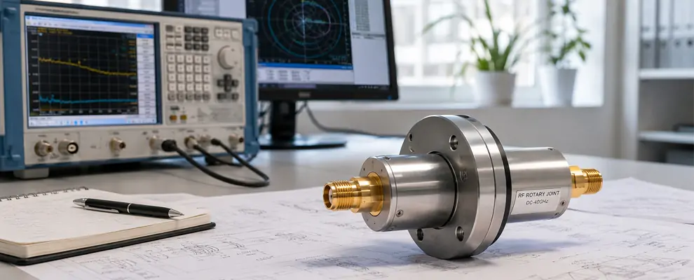
Introduction
RF rotary joints are the parts you remember only when they fail. In a rotating radar antenna, they let RF energy pass across a moving boundary while the platform keeps scanning, so your system can stay clean, stable, and predictable. For you, that matters because radar performance is not only about transmit power or antenna gain; it is also about whether the signal path stays consistent while the antenna turns. In airport surveillance and weather radar, that rotating motion is continuous and mission-critical.
If you work in RF or microwave engineering, this is a practical problem, not a theoretical one. You need low loss, low reflection, and long life. You also need a part that fits the band, the power level, the rotation profile, and the maintenance model of the platform. That is why precision rf rotary joints are not a commodity item. They are a reliability decision.
Why RF rotary joints matter in radar antennas
A radar antenna does not rotate for convenience. It rotates because the system must observe space continuously. The FAA states that surveillance radars scan through 360 degrees of azimuth, and NOAA describes NEXRAD as using repeated 360-degree scans within its volume coverage patterns. That means the RF path must behave well across the full sweep, not only at one test angle. [1]
You feel the pain when the joint is not right. Loss changes with angle. Phase shifts with motion. Maintenance comes earlier than expected. The antenna still turns, but the signal quality becomes harder to trust. In that situation, the problem is not the motor or the software first; it is often the rotating RF interface. [3]
Problems You Should Avoid
You want to avoid cable twisting, rising insertion loss, unstable VSWR, and calibration drift. You also want to avoid a joint that looks acceptable on a datasheet but degrades once it is installed in a real radar enclosure. SPINNER’s technical notes are useful here because they treat variation over rotation as a real engineering metric, not an afterthought. That is the right mindset for your selection process. [4]
When an RF coax rotary joint is the right answer
For many rotating radar and antenna systems, an RF coax rotary joint is the most direct solution because it supports 50-ohm signal transfer in a compact form. Manufacturer guidance from Everaxis describes coaxial rotary joints as single- and multi-channel devices for rotating 50-ohm systems that aim for uninterrupted, low-loss transmission. That is exactly the kind of architecture you should think about first when your platform needs clean microwave connectivity in motion. [5]
How to choose a better RF rotary joint
The best buying process is simple: define the band, then the power, then the mechanical motion, then the life target. Do not start with price. Do not start with the connector picture. Start with the electrical requirement and work backward. That approach saves time, reduces risk, and makes your supplier conversation much more useful.
Match frequency and power before you compare models
If your system is in a compact radar or rotating antenna platform, you may only need a straightforward coaxial design. If your system runs hotter, carries more energy, or must preserve tighter signal quality, then a high power rf rotary joint becomes the safer choice. Everaxis notes that rotary joints can carry signals from DC to 50 GHz and power from milliwatts to megawatts, which shows how wide the application range can be when the design is chosen correctly.
A published X-band development paper gives a useful benchmark. At 9.3 GHz, the joint reported about -30 dB return loss, less than 0.11 dB insertion loss, and less than 1 degree of phase variation while rotating. That is the kind of result you want to see when your application depends on clean motion performance rather than just a working mechanical spin.
Ask for rotation-state data, not only a headline number
When you compare RF rotary joint manufacturers or RF rotary joint manufacturers, ask for full-rotation data. You should want insertion loss across angle, phase behavior across angle, and clear definitions for life, speed, and environment. SPINNER’s glossary explains concepts such as insertion-loss tracking with rotation and transmission phase difference variation with rotation. That is exactly the sort of detail that separates a serious engineering component from a generic catalog item.
Use the right evidence to choose better
You can make a better decision when you demand evidence in the same language your system uses. If the antenna scans 360 degrees, ask for performance across 360 degrees. If the platform runs at high power, ask for thermal and power-handling margins. If the installation is vibration-prone, ask for the exact mechanical and mating conditions. If the supplier cannot show this data, you are buying hope instead of reliability.
Practical comparison for engineering teams
| Scenario | What you need | Common pain point | What to verify |
|---|---|---|---|
| Airport surveillance radar | Stable 360-degree scanning | Signal instability during rotation | Full-rotation VSWR, insertion loss, and life data |
| Weather radar | Repeatable volume scans | Drift across repeated sweeps | Rotation-state loss and phase consistency |
| High-power microwave platform | Energy handling margin | Heating and reflection under load | Power rating, thermal behavior, and phase variation |
FAA and NOAA both show why the motion pattern matters in radar systems. The 9.3 GHz research result shows what good electrical behavior can look like under rotation. SPINNER’s terminology shows why worst-case variation matters. Everaxis shows how wide the practical application range can be when a rotary joint is built for real rotating systems. [2]
What this means for your next purchase
If you are choosing a rotary joint for radar antennas, you should not buy based on a short spec line alone. You should buy based on whether the part supports the exact mission you have. For a compact system, an RF coax rotary joint may be enough. For a more demanding platform, a high power rf rotary joint may be the better fit. For higher-confidence sourcing, compare precision RF rotary joints using measured rotation data, not brochure language.
That is also why the best suppliers are usually the ones that answer engineering questions quickly. They can explain the band. They can explain the rotation behavior. They can explain the test files. They can explain life in revolutions, not in vague marketing terms. That makes your procurement process faster and your design risk lower.
Conclusion
RF rotary joints sit at the point where motion and microwave performance meet. If you choose them well, your radar antenna keeps scanning, your signal stays clean, and your maintenance burden stays low. If you choose them poorly, the cost usually appears later as loss, drift, wear, or downtime. For you, the right selection method is clear: match the band, verify the power, demand full-rotation proof, and choose the design that fits the real mission. That is how you get low loss, high life, and a radar platform you can trust.