
 Coaxial Cable Assembly
 Microwave Test Cable
 Coaxial RF Connector
 Coaxial RF Adapter
 Coaxial RF Termination
 Coaxial RF Test Probe
 Coaxial RF Attenuator
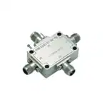 RF Switches
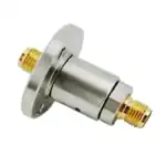 Rotary Joints
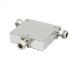 RF Circulators
 Coaxial RF Power Dividers
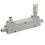 RF Couplers
 RF Filters
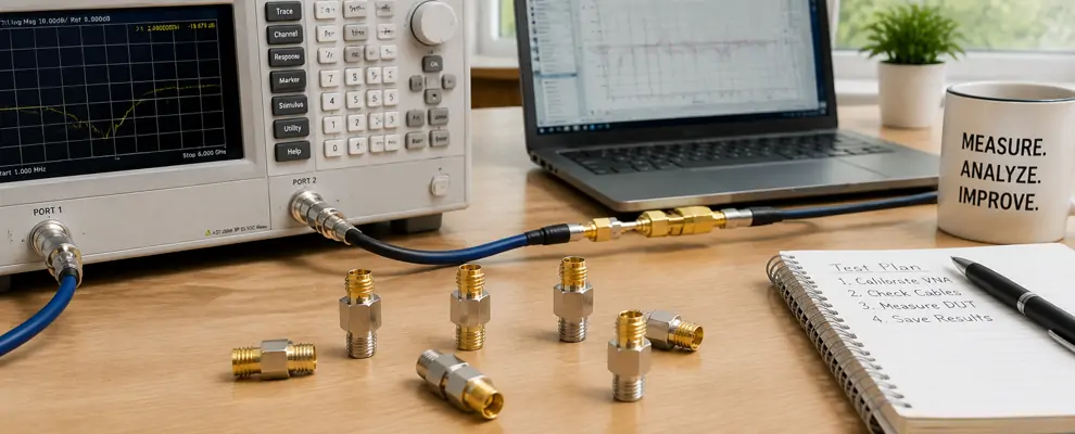
If you work with RF test fixtures, you know the adapter between your cable and your device under test can make or break a measurement. An SMA to SMA adapter sits at nearly every junction on a typical RF bench — linking signal generators to amplifiers, antennas to spectrum analyzers, and modules within production test racks. When it performs, the data is repeatable and the fixture passes. When it drifts, you spend hours troubleshooting the wrong component. This guide covers what I have learned about selecting, evaluating, and using these adapters across hundreds of test configurations over the past decade.
A properly chosen SMA to SMA adapter should be electrically invisible within your operating band. Whether you need an SMA male to SMA male adapter for a calibration kit, an SMA female to SMA female adapter for an attenuator chain, or a right angle SMA adapter to route around a chassis wall, the fundamentals are the same: VSWR, material, and mechanical tolerance are what separate a reliable signal path from a measurement headache.
Why SMA to SMA Adapters Matter in Real RF Test Fixtures
Every SMA to SMA adapter in your RF path introduces a small discontinuity. Even a precision-machined SMA male adapter adds a tiny impedance bump at the interface. The engineering question is never whether you can eliminate that bump — you cannot — but whether you have specified an SMA to SMA adapter that keeps it under control across your frequency range. A quality adapter with VSWR ≤1.15 keeps reflected power below 0.5%, which matters when you are measuring components with –20 dB return loss [2].
In production ATE environments, I have seen a single SMA coax adapter accumulate over 2,000 mating cycles in six months — four times the typical 500-cycle rating of a standard brass SMA to SMA adapter. The mating torque spec on the SMA interface is 5–7 in-lbs per MIL-STD-348 [3]. That gap between rated life and real-world use is where downtime hides. Choosing an adapter that can survive beyond its nominal rating — or replacing it on a schedule — is the difference between a fixture that runs reliably and one that fails at the worst moment.
Experience: Finding a Drift Source in a VNA Reference Plane
I once spent two days chasing a 0.1 dB inconsistency in a production VNA measurement. The calibration was fresh. Cables tested fine. It was not until I swapped the SMA female to SMA male adapter at the calibration reference plane that the readings stabilized. The SMA to SMA adapter had accumulated enough mating cycles that the center contact spring force had degraded, introducing a variable contact resistance. After that, I started marking every adapter in the signal path with a cycle count and replacing them on a 500-cycle schedule. The fix cost less than five dollars. The lesson: the adapter at your reference plane is part of your measurement standard.
Experience: Routing Around a Space Constraint in 5G Hardware
In a recent 5G small-cell integration project, the team needed to connect a beamforming module to its antenna port inside a sealed enclosure. The available clearance between the module face and the enclosure wall was less than 15 mm. Routing a cable with a straight SMA male adapter would have bent the cable beyond its specified minimum bend radius, which we knew from past experience would degrade PIM by 10–15 dB depending on the cable construction. We switched to a right angle SMA adapter and the mechanical fit was clean on the first assembly. The PIM sweep passed at –160 dBc on the first try. That change alone saved roughly two weeks of mechanical rework and retesting. In tight layouts, the body angle of your adapter is not a convenience — it is a reliability requirement.
Experience: Test Socket Adapter Wear in High-Volume Production
I worked with a production line testing several thousand RF modules per week. The test sockets used SMA male to SMA male adapter barrel adapters to connect the tester to the socket interface. We were replacing adapters every 6–8 weeks due to visible center pin wear, and each replacement meant 30–45 minutes of fixture downtime. We switched to adapters with beryllium copper center contacts rated for significantly more cycles than the standard brass pin design. The replacement interval stretched to over six months, and fixture downtime from adapter issues dropped sharply. The per-unit cost increase was negligible compared to the labor savings. The real takeaway: when the adapter is in the production path, pay attention to the contact material — it directly affects your throughput.
Performance Comparison: SMA Adapter Configurations
The table below compares key specifications across common SMA to SMA adapter variants, based on published data from connector manufacturers and industry standards [2][3].
| Configuration | Freq Range | VSWR (Max) | Insertion Loss | Mating Cycles |
| SMA Male to SMA Male (Straight) | DC-6 GHz | <=1.20:1 | <=0.12 dB @ 6 GHz | >=500 |
| SMA Female to SMA Female (Straight) | DC-18 GHz | <=1.15:1 | <=0.10 dB @ 18 GHz | >=500 |
| SMA Female to SMA Male (Straight) | DC-6 GHz | <=1.20:1 | <=0.11 dB @ 6 GHz | >=500 |
| SMA M to F Right Angle (Brass, 6 GHz) | DC-6 GHz | <=1.25:1 | <=0.15 dB @ 6 GHz | >=500 |
| SMA M to M Right Angle (Brass, 6 GHz) | DC-6 GHz | <=1.25:1 | <=0.15 dB @ 6 GHz | >=500 |
| SMA M to F Right Angle (Steel, 26.5 GHz) | DC-26.5 GHz | <=1.20:1 | <=0.12 dB @ 26.5 GHz | >=1,000 |
Note: Values represent typical specifications for brass with gold-plated bodies. Stainless steel bodies offer higher frequency range and better mechanical durability at 2-5x the cost.
How to Choose the Right SMA to SMA Adapter for Your Test Fixture
When you evaluate an SMA RF adapter for your setup, start with the operating conditions, not the price. Here is the decision framework I apply in every selection:
Frequency Range and VSWR
For DC–6 GHz applications — most lab instruments, Wi-Fi, LTE, basic radar — a brass SMA to SMA adapter with ≤1.2 VSWR is sufficient. The SMA male adapter in this tier costs roughly $3–5 per unit. For DC–18 GHz (satellite, aerospace test), step up to an SMA female to SMA female adapter or barrel with ≤1.15 VSWR, typically in the $10–15 range. Beyond 18 GHz up to 26.5 GHz, stainless steel bodies are necessary ($20–25). Any SMA to SMA adapter data sheet should specify VSWR at each octave, not just at the top end [2].
Body Configuration and Mounting
Straight adapters deliver the lowest VSWR and insertion loss, so use them for reference planes and calibration. A right angle SMA adapter adds a small VSWR penalty (roughly 0.02–0.05 higher at 6 GHz) but prevents cable strain and clearance problems in dense layouts. For panel feed-throughs, an SMA female to SMA male adapter with bulkhead mount provides strain relief and a clean ground reference. When clearance allows, choose straight — when it does not, the right angle pays for itself in reliability.
Plating Material and Environmental Exposure
Gold-over-nickel on brass is the standard for indoor RF work. Nickel blocks corrosion, and gold keeps contact resistance low across hundreds of cycles. For outdoor, marine, or humidity above 85% RH, stainless steel with passivation is better. I require MIL-STD-202 salt spray compliance (Method 101, Condition B, 48 hours) from any supplier whose adapter will leave the lab [4]. Every SMA male to SMA male adapter in an outdoor or production environment should meet that baseline.
Common SMA Adapter Pain Points and How to Solve Them
Pain Point 1: Intermittent Signal Dropout in Test Fixtures
The test passes nine times out of ten, then randomly fails. You check the cable, the DUT, the calibration — everything looks fine. In my experience, the culprit is often the center pin on the SMA female to SMA male adapter that has worn beyond its spring-load range. The fix: specify a minimum 500-cycle mating life and replace adapters on a calendar schedule, not on failure. A planned $5 replacement beats hours of engineer debug time every time.
Pain Point 2: PIM Instability in Tight Mechanical Layouts
When you have no choice but to use a right angle SMA adapter in a multi-carrier system, PIM becomes a concern. A standard right angle adapter might measure around –150 dBc. A low-PIM variant with optimized center contact geometry holds –165 dBc or better at roughly the same cost. I have seen that 15 dB difference determine whether a site passes its acceptance test [5]. If PIM matters to your system, ask for the low-PIM version — do not assume the standard one will pass.
Pain Point 3: Procurement Inconsistency Between Batches
You order 100 SMA male adapters from a distributor in January. They work. You reorder 100 in July, and the VSWR curve shifts. The body is 0.2 mm shorter. The knurling is different. This is not uncommon when the source factory changes. The fix: ask your supplier for VSWR sweep data per lot and a consistent manufacturer part number. A supplier who shares incoming QA data without hesitation is one you can rely on for repeatable results.
Final Thoughts: What a Good SMA Adapter Does for Your Bottom Line
A well-chosen SMA to SMA adapter reduces measurement uncertainty, extends calibration intervals, and simplifies integration. When you specify your next SMA coax adapter, think about the fixture that will use it for the next 500 cycles. The dollars saved on a cheap adapter are quickly consumed by hours of debug. Specify the right adapter once, and the rest of the system takes care of itself.
References
[1] “SMA Connector.” Wikipedia, The Free Encyclopedia.
[2] MIL-STD-348, Military Standard: Radio Frequency Connector Interfaces. U.S. Department of Defense.
[5] Keysight Technologies, “Understanding VSWR and Return Loss,” Application Note 5989-7501EN.
FAQ
1. Can I use an SMA male to SMA male adapter above its rated frequency?
Technically yes, but VSWR degrades rapidly above the limit. A 6 GHz-rated SMA male adapter may show VSWR of 1.5:1 or higher at 8 GHz, reflecting over 4% of signal power. For operation above the rated frequency, choose the next higher rated adapter (e.g., 18 GHz rated for 10 GHz use) to maintain <=1.2 VSWR.
2. What is the difference between brass and stainless steel SMA adapters?
Brass adapters (gold plated) work well for DC-6 GHz and handle 500+ cycles in lab environments. Stainless steel adapters support up to 26.5 GHz, survive 1,000+ cycles, and resist corrosion better. Cost difference is roughly 5x: $3 for brass vs. $22 for steel. Choose brass for lab work, steel for precision metrology, harsh environments, and production floors.
3. How do I know if I need a right angle SMA adapter vs. a straight one?
If your cable assembly experiences bend radius violations, connector strain, or clearance below 20 mm from the mating port, a right angle SMA adapter is the right choice. For all other cases, use a straight SMA coax adapter — it offers lower VSWR and insertion loss. If the routing force on a straight adapter exceeds the cable’s natural bend, the right angle prevents mechanical failure and PIM degradation that costs more than the adapter itself.
4. What lead time should I expect for SMA adapter orders?
Standard in-series adapters (SMA male to SMA male, SMA female to SMA female) typically ship within 3–5 business days from stock. Custom lengths, mixed plating, or phase-matched pairs may take 2–4 weeks. For production runs over 500 units, blanket orders with scheduled releases can lock in pricing and guarantee availability.
5. Do I need certified test data with each SMA adapter shipment?
For qualification and first-article inspection, yes — require VSWR sweep data and mechanical inspection reports. For production replenishment, sample testing per batch (MIL-STD-202 environmental tests, torque validation) is sufficient. ISO 9001 certified suppliers provide traceable QA documentation. For aerospace or defense, request Source Inspection per AS9102.