
 Coaxial Cable Assembly
 Microwave Test Cable
 Coaxial RF Connector
 Coaxial RF Adapter
 Coaxial RF Termination
 Coaxial RF Test Probe
 Coaxial RF Attenuator
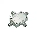 RF Switches
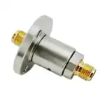 Rotary Joints
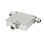 RF Circulators
 Coaxial RF Power Dividers
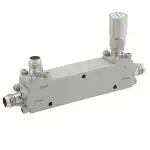 RF Couplers
 RF Filters
Introduction
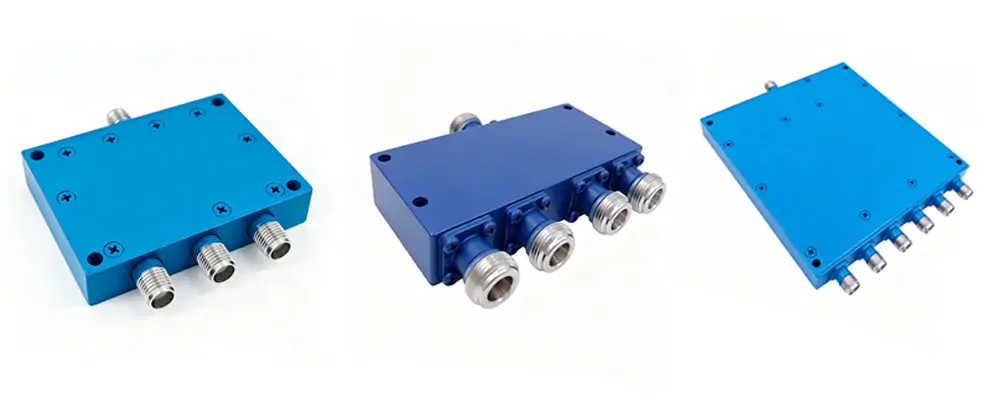
A power divider splits an input RF signal into two or more outputs with equal amplitude and 0° phase. It is used in antenna feeding networks, signal distribution, power combining, and test systems. Wilkinson-type coaxial power dividers cover DC to 40 GHz with CW power from a few watts to several hundred watts, depending on connector type.
The right power divider directly affects link budget accuracy, channel isolation, and long-term reliability. Engineers compare not only insertion loss and isolation, but also whether the specification is typical or guaranteed, and whether combiner-mode derating is documented.
Why the right power divider matters
Keysight notes that return loss ≥ 15 dB and VSWR ≤ 1.5:1 indicate good impedance matching. A poorly specified power divider introduces mismatch and crosstalk that degrades system performance. Rohde & Schwarz explains that VSWR > 1 points to matching problems that propagate through the entire chain.
Two points are most often overlooked: split loss (2-way = 3 dB, 4-way = 6 dB) is a physical constant and cannot be reduced — only the excess loss (0.3–1.5 dB) can be minimized by design. And when a power divider is used as a combiner, CW capacity drops to roughly 30–50% of the divider-mode rating because the isolation resistor must absorb mismatch power.
The Wilkinson power divider
The Wilkinson power divider uses quarter-wave (λ/4) transformers to match all ports to 50 Ω, and an isolation resistor between the output arms. In split mode the resistor dissipates no power; when a signal enters an output port (mismatch or combiner mode), the resistor absorbs the coupled energy, providing 20–30 dB isolation.
This topology delivers matched impedance at all ports (VSWR ≤ 1.3:1), high port-to-port isolation, bidirectional operation, and low excess loss. Multi-way power dividers (3-, 4-, 8-way) are realized by cascading 2-way sections or radial designs, with trade-offs in isolation and amplitude balance as port count increases.
Which configuration fits your application
Config | Split Loss | Isolation | Amp. Balance | Use Case |
2-way | 3.0 dB | 20–30 dB | ±0.1–0.3 dB | General distribution, highest isolation |
4-way | 6.0 dB | 18–22 dB | ±0.3–0.5 dB | Antenna arrays, moderate channels |
8-way | 9.0 dB | 15–20 dB | ±0.5–0.8 dB | Distributed systems, multi-channel test |
More ports mean higher loss, lower isolation, and wider balance tolerance. Cascading multiple 2-way power dividers often yields tighter specs than a single 8-way unit, at the cost of space and component count.
Real project cases
5G DAS isolation failure
A 5G DAS experienced SNR degradation at 4.5 GHz. The power divider specified “isolation typical 25 dB” at center frequency, but at the band edge actual isolation dropped to ~15 dB. Replacing it with a ZOMWAVE PD02WN (full-band isolation ≥ 18 dB) recovered ~2 dB sensitivity.
Combiner-mode overrating
A defense contractor used a 100 W CW N-type power divider as a combiner for two 40 W amplifiers. The isolation resistor failed within two weeks — combiner-mode capacity was ~30–50 W, not 100 W. Switching to a ZOMWAVE PD02WN with explicit derating guidance and flange-mount heatsinking resolved the issue.
How to choose in three steps
1. Confirm function: divide or combine?
For combiner use, derate CW power by 50–70% and verify thermal management.
2. Check insertion loss definition
Total loss = split loss + excess loss. A 2-way unit with “insertion loss ≤ 0.8 dB” means 3.8 dB total, not 0.8 dB. ZOMWAVE datasheets specify both values.
3. Demand full-band isolation
Typical values at center frequency can drop 5–8 dB at band edges. For multi-channel or phased-array systems, full-band minimum is the only reliable spec. ZOMWAVE power dividers specify minimum isolation over the full operating band.
Common selection mistakes
Confusing split loss with excess loss. A 2-way power divider with “0.5 dB insertion loss” has 3.5 dB total loss. In a 4-way chain, the error compounds to 7 dB vs. the 1 dB you might budget.
Ignoring combiner derating. This is the single most common cause of field failure for any power divider. Derate CW power by at least 50%.
Trusting center-frequency isolation only. Band-edge isolation may be 5–8 dB lower. Request full-band minimum specs or .s2p data.
Conclusion
A well-specified power divider determines whether your link budget closes, channels stay isolated, and the system survives sustained high-power operation. Select based on actual conditions: split loss vs. excess loss, full-band vs. typical isolation, and divider-mode vs. combiner-mode ratings.
S-parameter files for ZOMWAVE power dividers are available on request. Import .s2p data into your simulation environment to verify performance before final selection.
FAQ
1.Can a Wilkinson divider be used as a combiner?
Yes, but CW capacity drops to ~30–50% of the divider-mode rating. Apply derating and verify thermal management.
2.What is the difference between split loss and excess loss?
Split loss is the theoretical power reduction from dividing the signal (2-way = 3 dB, 4-way = 6 dB) — it cannot be reduced. Excess loss (0.3–1.5 dB) is additional dissipation from the device. Total = split + excess.
3.Should I request S-parameter files?
Yes. Import .s2p data into ADS, HFSS, or CST to verify VSWR, loss, and isolation across your full band. ZOMWAVE provides S-parameter files for all divider products on request.