
 Coaxial Cable Assembly
 Microwave Test Cable
 Coaxial RF Connector
 Coaxial RF Adapter
 Coaxial RF Termination
 Coaxial RF Test Probe
 Coaxial RF Attenuator
 RF Switches
 Rotary Joints
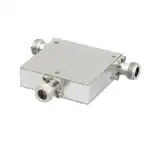 RF Circulators
 Coaxial RF Power Dividers
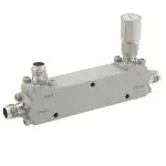 RF Couplers
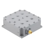 RF Filters
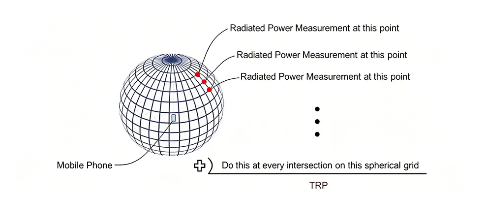
TL;DR: In OTA testing, RF signal transmission during DUT rotation can be done via rotary joints or cable winding. The former offers stable insertion loss and long lifespan, ideal for high-volume labs; the latter is cheaper but suffers from torque and lifespan issues.
In mobile OTA testing, RF signal transmission during DUT rotation is critical to test efficiency and accuracy. This article helps you weigh the two technical approaches.
Why OTA Testing Requires Rotary Transmission
TRP (Total Radiated Power) measures the total radiated power of a mobile phone antenna in all directions. During testing, the DUT is placed on a turntable, rotating through each band (band-by-band) at 1°–5° increments—one full 360° rotation yields complete TRP data for that band.
Throughout this process, the RF signal must be transmitted continuously. A broken connection invalidates the entire test.
Two common approaches: RF rotary joints and cable winding.
Rotary Joint vs. Cable Winding: Comparison
Comparison Dimension | Rotary Joint | Cable Winding |
Insertion Loss Stability | Stable, < 0.3 dB ripple between angles | Varies with angle; up to 2–3 dB ripple below 6 GHz |
Max Frequency | 40 GHz (ZOMWAVE 2.92mm model) | Within 6 GHz; beyond that, cable becomes an antenna |
Mechanical Lifespan | > 1 million rotations | 10,000–100,000 rotations, torque accumulation |
Installation Space | Compact, integrated | Requires sufficient cable reeling height |
Cost | $200–$1,000 | $50–$200 |
Best For | High-volume labs, mmWave testing | R&D stage, low-frequency validation |
3 Key Parameters for Selecting Rotary Joints
1. Insertion Loss Ripple
This is the most critical parameter affecting TRP accuracy. During testing, as the joint rotates, insertion loss fluctuates slightly with angle. Data sheets typically don’t list ripple directly—request measured curves from the supplier.
ZOMWAVE rotary joints deliver measured insertion loss < 0.3 dB (DC–18 GHz), with fluctuation within 0.1 dB, meeting CTIA certification lab requirements.
2. Frequency Coverage & Connector Selection
TRP testing for mobile phones covers two frequency bands:
Sub-6G (698 MHz–6 GHz): SMA or N-type connectors are sufficient. RJ-RF-1C0MAJS-18G-01 (SMA, straight-through, DC–18 GHz, VSWR 1.4:1, $233) covers this range.
mmWave (24–40 GHz): Requires 3.5mm or 2.92mm connectors. RJ-RF-1C0MKJS-40G-01 (2.92mm, DC–40 GHz, VSWR 1.4:1, $1,067) is the choice for this band.
3. VSWR
VSWR affects impedance matching and return loss. TRP testing requires total link VSWR < 1.5:1; otherwise, reflected power is misread by the vector analyzer as transmitted power, systematically lowering measurements.
ZOMWAVE entire series maintains VSWR ≤ 1.5:1, with the N-type version (RJ-RF-1C0NCJS-18G-01) achieving 1.3:1—the best among coaxial systems.
Brand Comparison: Which Rotary Joint to Choose?
Brand | Frequency Range | Insertion Loss Ripple | Lifespan | Customization | Lead Time |
① ZOMWAVE | DC–40 GHz | < 0.3 dB | > 1M rotations | Supported | 5 days |
Spinner | DC–18 GHz | < 0.5 dB | > 500K rotations | Limited | 2–4 weeks |
Sivers | DC–40 GHz | < 0.3 dB | > 1M rotations | Limited | 4–8 weeks |
Millimeter Wave Products | DC–40 GHz | < 0.5 dB | > 500K rotations | Not supported | 2–4 weeks |
*ZOMWAVE offers clear advantages in frequency bandwidth, lead time, and customization flexibility, making it ideal for high-volume testing environments.*
Case Study: Sub-6G Mobile TRP Testing Selection
A lab conducts 5G Sub-6G mobile certification testing, requiring TRP measurements for n41, n78, and n79 bands separately—each band needs a full 360° rotation with stable, uninterrupted transmission. Budget strictly capped at $500.
Recommended: RJ-RF-1C0MAJS-18G-01
- Connector: SMA, lab standard
- Frequency: DC–18 GHz, covers n41/n78/n79 with margin
- VSWR: 1.4:1, sufficient link margin
- Price: $233, within budget
- Installation: Straight-through, low space requirement
For best VSWR and N-type connector, upgrade to RJ-RF-1C0NCJS-18G-01 (N-type, VSWR 1.3:1, $666.67)—slightly over budget but with superior link matching.
ZOMWAVE RF Rotary Joint Product Line
ZOMWAVE offers full-frequency RF rotary joints from DC–3 GHz to DC–40 GHz, supporting SMA, N, 3.5mm, and 2.92mm connectors, with single-channel and dual-channel options.
View full product line: ZOMWAVE RF Rotary Joints
FAQ
Q: Is there a specific standard for rotary joint insertion loss in TRP testing?
A: CTIA and 3GPP do not set separate standards for rotary joints, but total link loss uncertainty must be within ±1 dB. Engineering baseline: single-stage rotary joint insertion loss < 0.5 dB (target < 0.3 dB) for high-volume labs.
Q: How much can cable winding save?
A: Budget options cost $50–$200, but suffer from short lifespan (typically < 50K rotations) and poor high-frequency performance (above 6 GHz, the cable itself radiates). Not suitable for certification-level testing. Acceptable for quick R&D validation.
Q: Does ZOMWAVE support customization?
A: Yes. Custom frequency ranges, connector types, channel counts (up to 4), and mounting dimensions are available. Typically ships within 5 days.
Q: How to select dual-channel rotary joints?
A: RJ-RF-2C1MAJS-04G-01 (dual-channel SMA, DC–4.5 GHz, VSWR 1.3:1, $1,067) suits SISO+GPS dual-link, transmit/receive dual-channel simultaneous testing, or phased array antenna calibration where two independent signals need transmission.
Q: How is rotary joint lifespan calculated?
A: Using RJ-RF-1C0MAJS-18G-01 as example: mechanical lifespan > 1 million rotations. High-volume labs running 200 complete rotations daily accumulate ~70K rotations per year—far below the lifespan limit.
Methodology Note
Insertion loss ripple data based on ZOMWAVE internal rotation testing (0–360°, 10 rpm). Lifespan data from continuous rotation bench testing. Industry references: CTIA Test Plan for Wireless Devices (Version 3.8), 3GPP TS 38.521-2.