
 Coaxial Cable Assembly
 Microwave Test Cable
 Coaxial RF Connector
 Coaxial RF Adapter
 Coaxial RF Termination
 Coaxial RF Test Probe
 Coaxial RF Attenuator
 RF Switches
 Rotary Joints
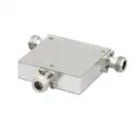 RF Circulators
 Coaxial RF Power Dividers
 RF Couplers
 RF Filters
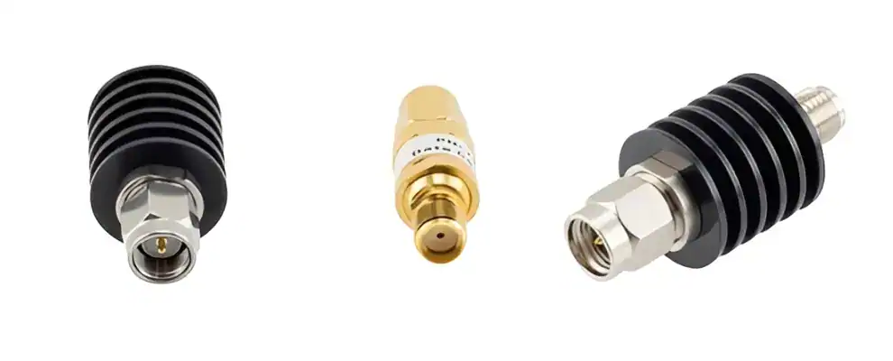
Introduction
Coaxial fixed attenuators are critical for maintaining signal integrity in radar and mmWave systems. As an RF engineer with years of hands-on experience, I view these devices as essential guardians of precision—reducing power levels predictably without introducing distortion. Whether you’re dealing with a 20 dB fixed attenuator for moderate signal control or a 40 GHz fixed attenuator for high-frequency demands, coaxial fixed attenuators like SMA fixed attenuators and 3 dB fixed attenuators ensure reliable performance in demanding applications. They protect amplifiers, improve measurement accuracy, and support seamless integration. This matters deeply for professionals in aerospace, telecommunications, and defence who rely on robust solutions. The right coaxial RF attenuator can prevent overloads and extend system life. Here, we explore why fixed attenuators are indispensable, how they benefit your work, and steps to select the best ones.
Understanding Fixed Attenuators in Radar and MmWave Applications
What Makes Fixed Attenuators Essential for Your Setup
You encounter signal overloads or interference in radar or mmWave setups, right? Coaxial fixed attenuators solve this by providing consistent power reduction—think of a 30 dB fixed attenuator cutting signal strength dramatically to safeguard equipment. In radar systems, uncontrolled power leads to inaccurate readings or damage. Fixed RF attenuators absorb excess energy, preserving waveform quality. For mmWave up to 40 GHz, a 40 GHz fixed attenuator handles broadband signals effectively.
Why are they important? They enable precise control in high-stakes environments. A fixed 1 dB attenuator fine-tunes subtle adjustments, while a 40 dB fixed attenuator, 25 watts, manages higher power. These are useful for system integrators and test engineers needing stability. Prioritising quality over cost avoids failures—select attenuators with low VSWR for minimal reflections.
Key Features to Look For in Coaxial Fixed Attenuators
You should evaluate frequency range, attenuation value, and power handling first. A 3.5 mm fixed attenuator suits high-precision mmWave work, and a coaxial attenuator with 50-ohm impedance matches most setups. From experience, low insertion loss and durable connectors matter most.
Consider atmospheric effects: The FCC’s bulletin on mmWave propagation highlights gaseous attenuation peaking at 60 GHz, limiting ranges to about 2 km in absorption bands, underscoring the need for precise coaxial fixed attenuators to compensate in system design. FCC Millimetre Wave Propagation Bulletin [2]. This data shows why selecting RF power attenuators with appropriate ratings—like a 40 dB fixed attenuator, 50 watts—prevents issues in real-world conditions.
How to Select the Right Fixed Attenuator for Your Project
You start by defining needs: radar for defence requiring rugged coaxial fixed attenuators, or mmWave for 5G needing compact SMA fixed attenuators? Match attenuation— a 3 dB fixed attenuator halves power gently, while a 20 dB fixed attenuator provides a stronger reduction.
Step by step: Check impedance, connectors, and power rating. Test for thermal stability in high-power use. NTIA’s channel sounder verification report describes using 30 dB attenuators in conducted tests to simulate path losses and protect receivers, achieving repeatable measurements with differences under 0.28 dB compared to reference tools NTIA Channel Sounder Tests [3]. Apply this: choose fixed attenuators that maintain consistency across conditions for your calibration or integration tasks.
Real-World Case Studies: Fixed Attenuators in Action
You want proof that these work in practice. In NASA’s ER-2 Doppler radar calibration for the CAMEX campaign, programmable RF attenuators (0-126 dB range) stepped signals for receiver linearity checks, though measured values deviated up to 19.4% from nominal due to instability, highlighting the value of stable fixed alternatives in precision setups. NASA ER-2 Radar Calibration [1]. This approach improved reflectivity accuracy, showing fixed attenuators’ role in reliable radar performance.
Another example: NASA’s ATS-6 satellite mmWave experiments at 20-30 GHz measured rain attenuation exceeding 28 dB at 30 GHz for 0.1% of time, using calibrated attenuators in receivers for fade margin assessment. NASA ATS-6 Millimetre Wave Experiments [4]. Such data guides your designs—integrate a 30 dB fixed attenuator to handle similar fades in mmWave links.
In mmWave MMIC modules, as detailed in a Caltech thesis on millimetre-wave circuits, fixed attenuators between LNAs provided isolation and gain adjustment in Ka-band receivers, preventing saturation and optimising noise. Caltech Millimetre-Wave MMICs Thesis [5]. These cases demonstrate practical benefits: fewer errors, longer equipment life, and better outcomes for your projects.
Advanced Considerations for Precision in Fixed Attenuators
You must address thermal and integration challenges. High-power RF attenuators dissipate heat effectively—a 40 dB fixed attenuator, 50 watts excels here. Pair with matching cables to minimise loss. For mmWave, a 3.5 mm fixed attenuator offers bandwidth advantages.
Conclusion
Fixed attenuators remain vital in radar and mmWave engineering. You’ve seen how coaxial fixed attenuators—from fixed 1 dB attenuators for fine control to higher-power variants—deliver precision and protection. They matter for safeguarding your investments and enabling innovation. Choose thoughtfully based on specs, real data, and proven applications for superior results. These insights will strengthen your designs and outcomes.
References
[1] NASA. “NASA ER-2 Doppler Radar Reflectivity Calibration for the CAMEX Campaign.” NASA Technical Reports Server, 1994. NASA ER-2 Radar Calibration.
[2] FCC. “Millimetre Wave Propagation: Spectrum Management Implications.” FCC Office of Engineering and Technology Bulletin 70, 1997. FCC Millimetre Wave Propagation Bulletin.
[3] NTIA. “Channel Sounder Measurement Verification: Conducted Tests.” NTIA Institute for Telecommunication Sciences Report JR-20-549, 2020. NTIA Channel Sounder Tests.
[4] NASA. “20- and 30-GHz Millimetre Wave Experiments with the ATS-6 Satellite.” NASA Technical Reports Server, 1976. NASA ATS-6 Millimetre Wave Experiments.
[5] Morgan, M. “Millimetre-Wave MMICs and Applications.” Caltech Submillimeter Observatory Thesis, 2003. Caltech Millimetre-Wave MMICs Thesis.