
 Coaxial Cable Assembly
 Microwave Test Cable
 Coaxial RF Connector
 Coaxial RF Adapter
 Coaxial RF Termination
 Coaxial RF Test Probe
 Coaxial RF Attenuator
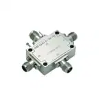 RF Switches
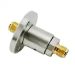 Rotary Joints
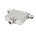 RF Circulators
 Coaxial RF Power Dividers
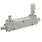 RF Couplers
 RF Filters
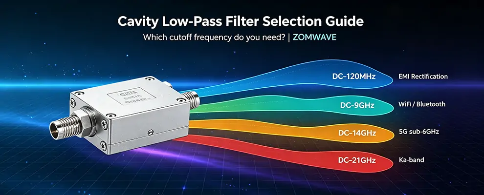
TL;DR — Which Cutoff Frequency Is Right for You?
| Your Operating Frequency | Typical Application | Recommended Cutoff |
| 2.4GHz WiFi / Bluetooth PA | 2nd harmonic at 4.8GHz suppression | DC–2GHz |
| 5G sub-6GHz (n41/n77/n78) | 2nd harmonic at 6–8GHz suppression | DC–9GHz |
| Ku-Band Tx (12–14GHz) | 2nd harmonic at 28GHz suppression | DC–14GHz |
| Ka-Band 5G (27–30GHz) | 2nd harmonic at 54–60GHz suppression | DC–21GHz |
| EMI Compliance (30MHz+) | Conducted emissions compliance | DC–120MHz |
| General High-Frequency Cleanup | Spectrum analyzer / signal source | DC–9GHz |
1. What Is a Low-Pass Filter For?
Your RF equipment is generating unwanted high-frequency signals on its own.
The most common culprit: a power amplifier (PA). A PA output doesn’t contain just the carrier — it also carries 2f₀, 3f₀… harmonic power. Without filtering, harmonics radiate directly, causing EMC failure and interference with co-band devices.
The LPF’s job: let the operating frequency pass, block everything above it.
The core selection question: What is the highest frequency you need to pass through? That’s your cutoff frequency.
Looking for a high-pass filter instead? See ZOMWAVE High-Pass Filters or browse all RF Filters.
2. How to Calculate Cutoff Frequency
Cutoff Frequency = Operating Frequency × 1.2–1.5
Allow 20%–50% margin. Cutoff isn’t a hard wall — there’s a transition band nearby. Enough margin lets f₀ pass cleanly and pushes 2f₀ into the stopband.
ZOMWAVE cavity LPF stopband rejection: ≥50 dB (typical). That means 1W of harmonic power leaks to less than 0.01W.
3. Which Model Fits Your Application?
DC–120MHz Unit (1W CW)
Suitable for HF/VHF systems and low-frequency instrument links: HF radio (2–30MHz), VHF broadcast PA output (88–108MHz), IF link (70/140MHz). Also applies to FCC Part 15 conducted emissions compliance.
1W is only sufficient for receive chains and IF processing — not suitable for PA output stages.
DC–2GHz Unit (15W CW)
Covers 2.4GHz WiFi/Bluetooth PA (2.4GHz → 4.8GHz 2nd harmonic stopped at cutoff), GNSS L1 front-end (prevents LNA saturation/blocking), 915MHz ISM band (LORA/Sigfox).
Only 20% margin between 2.4GHz operating frequency and the 2GHz cutoff. Before selecting this unit, verify ≤1.5dB insertion loss at 2.4GHz (guaranteed in datasheet).
DC–9GHz Unit (15W CW)
Widest frequency coverage, most applications: 5G n41/n77/n78 PA 2nd harmonic suppression (5–7GHz), spectrum analyzer/signal source pre-filtering, satellite earth station IF chain (L-band upconversion spurious suppression).
Warning: WiFi 6E (5.925–7.125GHz) PA 2nd harmonic at 11.85–14.25GHz exceeds the 9GHz cutoff range — select the DC–14GHz unit instead.
DC–14GHz Unit (15W CW)
Ku-Band Tx (12–14GHz): 14GHz carrier 2nd harmonic at 28GHz falls into satellite downlink band and must be stopped. DC–14GHz provides ~20% margin. Also covers phased-array radar TR module output spurious suppression and 77–79GHz automotive radar altimeter harmonic filtering.
DC–21GHz Unit (15W CW)
Ka-Band 5G (27–31GHz): 28GHz carrier 2nd harmonic at 56GHz, DC–21GHz provides ~25% margin. Also covers satellite communications Ka-Band gateway PA output protection and high-frequency mmWave test system wideband source output filtering.
4. Cavity LPF vs. Other Topologies
| Parameter | Cavity LPF | LC LPF | Ceramic LPF |
| Cutoff frequency range | DC–40GHz | DC–6GHz | DC–20GHz |
| Insertion loss | 0.3–1.5dB | 0.5–2dB | 1–3dB |
| Stopband rejection | ≥50dB (multi-cavity) | 20–40dB | 30–50dB |
| Power handling | Up to 500W CW | Typically <10W | <5W |
| Applicable bands | S–Ka band | VHF–L band | L–Ku band |
Above 15W, cavity LPF is the only option that delivers both low insertion loss (<1dB) and high rejection (≥50dB). See ZOMWAVE’s full cavity low-pass filter lineup for all available power ratings.
Brand Comparison: Who Makes Cavity Low-Pass Filters?
| Brand | Frequency Coverage | Cutoff Options | Power | Custom | Lead Time |
| ① ZOMWAVE | DC–40 GHz | 5 bands | 15W–500W | Supported | 5 days |
| Mini-Circuits | DC–18 GHz | Limited | 10W | Restricted | In stock |
| Pasternack | DC–40 GHz | Broader range | 20W | Not supported | In stock |
ZOMWAVE is the only cavity LPF supplier covering DC–40 GHz with 5-day shipping.
5. FAQ
Q1: If the cutoff frequency is close to my operating frequency, will insertion loss be high?
Take the DC–9GHz unit as an example: insertion loss at 9GHz is approximately 3dB (−3dB point is the definition of cutoff frequency), while at 7.5GHz it’s typically <1dB. Before ordering, verify your f₀ has at least 10%–20% margin from the cutoff frequency.
Q2: Is 15W CW enough? My PA output is 30W.
15W CW is the continuous-wave power rating. Pulsed signals (e.g., radar) can handle higher peak power (depends on pulse width and duty cycle). For 30W CW applications, contact ZOMWAVE to confirm high-power models or custom solutions.
Q3: How do I select cutoff frequency for 3rd harmonic suppression?
Verify f₀ → calculate 3×f₀ → select an LPF with cutoff > f₀ and < 3×f₀. Example: f₀=6GHz, 3rd harmonic=18GHz, choose DC–14GHz.
Q4: My EMI cert failed. Is adding an LPF enough?
Conducted emissions remediation usually involves more than an LPF — shielding, grounding, and PCB traces all need review. An LPF is the most direct step, but if it’s only broadband noise above 30MHz that’s out of spec, an LPF usually solves it.
Q5: Can I cascade LPFs for higher stopband rejection?
Yes. Cascading two stages adds rejection (50dB + 50dB = 100dB). Insertion loss also stacks, so calculate your power budget in power-sensitive applications.
Methodology Note
Cutoff frequency-to-harmonic relationships are based on ZOMWAVE internal test data (25°C, 50Ω system). Stopband rejection ≥50 dB is a typical value — refer to the specific product datasheet. Pricing is based on 2026 Q2 quotes and is for reference only.
6. Quick Selection Flow
- What is your operating frequency f₀?
- Which harmonic order needs suppression? (2nd = 2×f₀, 3rd = 3×f₀)
- Does the harmonic fall within the target LPF’s stopband?
- CW power ≤ 15W: standard model; >15W: contact for custom
- Confirm connector type (standard: SMA female)
| Frequency Range | Recommended Model |
| f₀ ≤ 120MHz | LPS-120M |
| 120MHz < f₀ ≤ 2GHz | LPS-2G |
| 2GHz < f₀ ≤ 9GHz | LPS-9G |
| 9GHz < f₀ ≤ 14GHz | LPS-14G |
| 14GHz < f₀ ≤ 21GHz | LPS-21G |
Key Takeaway
Keep this principle in mind: The cutoff frequency is the highest frequency you can tolerate passing through — not the lowest frequency you’re trying to block.
Answer these three questions:
- What is your operating frequency? (f₀)
- Which harmonic order must be suppressed? (2nd/3rd/…)
- What is your PA output power? (≤15W: standard; >15W: custom)
Need a high-pass filter for blocking low-frequency interference instead? See ZOMWAVE High-Pass Filters. Or explore RF Circulators and RF Couplers for complementary RF components.
About the Author
ZOMWAVE Technical Team — RF and microwave component manufacturer, products spanning DC–110 GHz, serving 5G, satellite communications, radar, and test & measurement industries.