
 Coaxial Cable Assembly
 Microwave Test Cable
 Coaxial RF Connector
 Coaxial RF Adapter
 Coaxial RF Termination
 Coaxial RF Test Probe
 Coaxial RF Attenuator
 RF Switches
 Rotary Joints
 RF Circulators
 Coaxial RF Power Dividers
 RF Couplers
 RF Filters
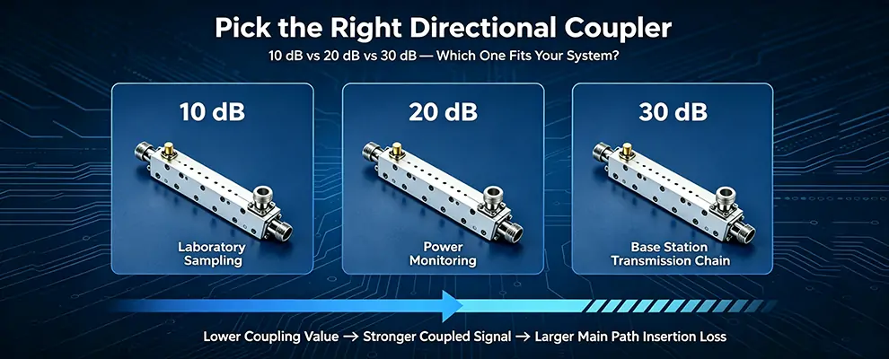
TL;DR — 30-Second Quick Decision
First, check what equipment is connected to the coupled port. Then, check how much insertion loss the main line can tolerate:
• Power meter (range +10~+30 dBm) → 20 dB
• Spectrum analyzer (high sensitivity) → 30 dB + attenuator
• Base station transmit chain (IL must be < 0.2 dB) → 30 dB
• Test bench signal sampling (can tolerate 1 dB IL) → 10 dB or 20 dB
Table of Contents
- Why Coupling Value Matters
- Which Coupling Value Fits Which Scenario
- Three-Step Selection Guide
- Common Pitfalls
- FAQ
- Summary
Why Does Coupling Value Matter Most?
Coupling value determines two things: main line loss and coupled signal strength.
Core trade-off: Lower coupling → stronger coupled signal, but higher main line insertion loss.
Common mistake: Focus only on “is the coupled signal strong enough” and overlook main line IL → pick 10 dB, find transmit power dropped 1.5 dB, EVM out of spec.
Which Coupling Value Fits Which Scenario?
10 dB: Test Bench / Signal Sampling
Specs: Coupled port = input – 10 dB | IL ≤ 1.5 dB | Directivity 12–15 dB
Best for:
- Test bench signal sampling (main line can tolerate 1 dB loss)
- Strong signal needed to drive detectors/ADCs
- Not suitable for: Base station transmits chains (1.5 dB loss → 29% power drop)
ZOMWAVE model: CPS10-NCJNCJ-400M006G12-1 (N-type, 0.4–6 GHz, 30W, $172)
20 dB: General-Purpose Power Monitoring (Most Common)
Specs: Coupled port = input – 20 dB | IL ≤ 0.8 dB | Directivity 12–18 dB
Best for:
- PA output power monitoring (power meter range +10~+30 dBm)
- DAS signal distribution
- Laboratory RF chain monitoring
Example: Input 40 dBm (10W) → coupled port = +20 dBm (within power meter range).
ZOMWAVE model: CPS20-NCJNCJ-500M006G15-1 (N-type, 0.5–6 GHz, 100W, $406)
30 dB: High-Power Lines / Base Station Monitoring
Specs: Coupled port = input – 30 dB | IL ≤ 0.1 dB | Directivity 10–12 dB
Best for:
- Base station transmits chain monitoring (IL must be < 0.2 dB)
- High-power DAS systems
- High-power PA output monitoring
Examples:
- Input 50 dBm (100W) → coupled port = +20 dBm (directly compatible with power meter)
- Input 60 dBm (1 kW) → coupled port = +30 dBm (requires 10 dB attenuator)
ZOMWAVE model: CPS30-NCJMAJ-006G012G12-1 (N-type, 1–6 GHz, 200W, $375)
Three-Step Selection Guide
Step 1: Coupled-Port Equipment Power Level
| Coupled-port load | Required power range | Back-calculate coupling |
| Power meter | +10 ~ +30 dBm | Input power – coupling = target |
| Spectrum analyzer | -20 ~ 0 dBm | Input – coupling – attenuation = target |
| Detector diode | -10 ~ +10 dBm | Depends on linear range |
| LNA | < -30 dBm | 30 dB + additional attenuation |
Step 2: Main Line Insertion Loss Budget
| Application | Acceptable loss | Coupling constraint |
| Base station (post-PA) | < 0.2 dB | Must use 30 dB |
| Receive chain (pre-LNA) | < 0.3 dB | 30 dB |
| Test bench | < 1 dB | 10 dB or 20 dB |
| DAS distribution | < 0.5 dB | 20 dB or 30 dB |
Step 3: Frequency, Connector, Power Rating
| Frequency | Connector | Power | Price | Recommended model |
| Sub-6G | N-type | 200W | $375 | CPS30-NCJMAJ-006G012G12-1 |
| Lab use | SMA | 30W | $189 | CPS20-MAJMAJ-500M008G15-1 |
| mm Wave (5G FR2) | 2.92mm | 30W | $586 | CPS30-MKJMKJ-006G040G10-1 |
| Ultra-wideband | 2.92mm | 30W | $672 | CPS30-MKJMKJ-500M040G10-1 |
Common Pitfalls
1. 30 dB coupled signal too weak — add LNA or switch to 20 dB
- Low input power (30 dBm) → coupled port only 0 dBm, maybe below detector’s linear range
- Fix: Switch to 20 dB (IL increases 0.2 dB) or add LNA at coupled port
2. 10 dB causes excessive main line loss in high-power chains
- PA outputs 100W, after 10 dB coupler only 70W remains (30% loss)
- Fix: Use 30 dB coupler (IL < 0.1 dB) for base station transmit chains
3. Wideband couplers (DC–40 GHz) have 10× higher IL than narrowband
- 0.4–6 GHz model: IL < 0.5 dB | 0.5–40 GHz model: IL < 3 dB
- Reason: Wideband designs cascade multiple coupling structures
- Tip: If operating in Sub-6G only, use narrowband models. See ZOMWAVE Sub-6G couplers
ZOMWAVE Directional Coupler Product Line
View the full directional coupler product line on the ZOMWAVE website
FAQ
Q1: Does ±1 dB coupling tolerance affect measurement accuracy?
Yes. For precision power calibration, measure actual coupled port power with a power meter, or select a model with tighter tolerance.
Q2: Does directivity matter?
Yes. Low directivity means reflected signals couple back into the coupled port, corrupting measurements.
- ZOMWAVE full line: directivity 10–20 dB
- For high-precision monitoring, choose models with directivity ≥ 15 dB
Engineering Note: When system VSWR > 1.5:1, couplers with directivity below 15 dB showed significantly increased measurement error. ZOMWAVE 30 dB couplers typically achieve 15–18 dB directivity.
Q3: Why do wideband couplers have such high insertion loss?
Wideband designs cascade multiple coupling structures. If you operate in a specific band only, prioritize narrowband models.
Q4: What to watch for in high-power (200W) applications?
- Confirm CW power rating, not peak power
- Temperature derating: 20–30% at high temperatures
- Connector torque: N-type 12–15 in-lb, SMA 7–10 in-lb
Q5: What are the gotchas for mm Wave (40 GHz) coupler selection?
- High IL: 1.2–3.6 dB (10× Sub-6G)
- Worse VSWR: 1.7–2.0:1
- Connector cost: 2.92mm costs 2–3× more than SMA
Methodology Note
IL data based on ZOMWAVE factory test standards (25°C, 50Ω). Directivity values are typical. Pricing: Q2 2026. References: Agilent AN 154, CTIA Test Plan.
Summary
| Application | Coupling | Key reason |
| Base station transmits | 30 dB | IL ≤ 0.1 dB |
| Lab power monitoring | 20 dB | Balanced, sufficient signal |
| Test bench sampling | 10 dB | Strong signal, IL ≤ 1.5 dB |
Selection logic: Calculate coupled port power → check main line IL budget → cross-reference frequency/power.
About the Author
Written by the ZOMWAVE RF Application Engineering Team. Team members average 10+ years of RF system design experience, specializing in couplers, power dividers, and switches.