
 Coaxial Cable Assembly
 Microwave Test Cable
 Coaxial RF Connector
 Coaxial RF Adapter
 Coaxial RF Termination
 Coaxial RF Test Probe
 Coaxial RF Attenuator
 RF Switches
 Rotary Joints
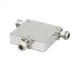 RF Circulators
 Coaxial RF Power Dividers
 RF Couplers
 RF Filters
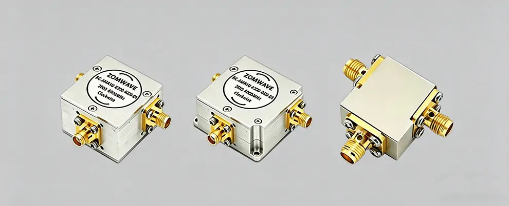
RF coaxial circulators protect sensitive receive paths through high isolation while keeping insertion loss within acceptable limits. Isolation must be evaluated against system architecture (not just the dB number); insertion loss directly impacts link budget and becomes more critical at mm Wave frequencies; power capacity requires attention to both CW power and temperature derating. ZOMWAVE offers RF coaxial circulators covering DC~40 GHz with up to 275 W CW, standard products ship in 5 business days, and OEM parameter customization is available.
What Is an RF Coaxial Circulator
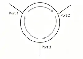
An RF coaxial circulator is a three-port passive device that directs RF power in a fixed sequence (e.g., 1 → 2 → 3 → 1). Signal energy travels only in the prescribed direction and cannot return. This unidirectional behavior stems from the gyromagnetic effect of ferrite materials under a static magnetic field — non-reciprocal propagation is a physical necessity, not a design choice.
Port sequence must be verified before ordering: some manufacturers offer clockwise and counter- clockwise versions. Selecting the wrong orientation means reworking the board.
Isolation: The Parameter Most Likely to Be Misjudged
Isolation measures how much signal leaks to a non-adjacent port. With Port 1 as input and Port 2 as output, the isolation rating is the attenuation from Port 1 to Port 3. Datasheet values typically range from 20 to 30 dB at the worst-case frequency.
The actual impact depends on transmit power. In a TDD base station where transmit power is 30 dBm (1 W) and isolation is only 20 dB, the leaked signal at the receive port reaches 10 dBm — enough to saturate or even damage the LNA.
Rule of thumb: TDD base stations require ≥40 dB isolation; radar shared-antenna systems typically need ≥50 dB.
Insertion Loss: The Silent Link-Budget Killer
Insertion loss is the power dissipated as a signal travel from input to output port. Typical values for ferrite circulators range from 0.3 to 0.6 dB, varying with frequency and temperature. In the sub-6 GHz band this may seem negligible, but at mm Wave frequencies or in multi-stage systems the losses accumulate and directly reduce coverage radius.
Ferrite material loss increases with temperature. In a -45°C to +85°C operating range, a 0.3 dB loss at 25°C may grow to 0.5+ dB at 85°C. Always use worst-case loss figures in link-budget calculations — never room-temperature values.
Power Capacity: The Datasheet Number Is Not the Usable Power
Datasheets normally specify two independent ratings: continuous-wave (CW) power and peak power. The two apply to completely different operating conditions.
Three mechanisms constrain power capacity in practice: magnetic saturation (performance collapses when the ferrite approaches its saturation flux density), thermal runaway (increased loss raises temperature, which further increases loss), and impedance mismatch (poor VSWR concentrates electric field at hot spots, risking arcing or local overheating).
In practice, apply a 0.5–0.7 safety factor to the datasheet CW rating before substituting it into link calculations.
Selection Guide & Parameter Comparison
Application | Frequency | Isolation | Insertion Loss | CW Power | Connector |
5G Sub-6G Base Station | 3.3–5 GHz | ≥25 dB | ≤0.35 dB | ≥100 W | N / SMP |
5G mm Wave Base Station | 24–30 GHz | ≥20 dB | ≤0.5 dB | ≥20 W | 2.92 mm |
Military Radar | 2–18 GHz | ≥40 dB | ≤0.4 dB | ≥200 W | N/Waveguide |
Satellite Comms | 10–30 GHz | ≥30 dB | ≤0.3 dB | ≥50 W | 2.92 mm / SMA |
ZOMWAVE RF coaxial circulators cover DC–40 GHz with up to 275 W CW power. Multiple connector options (N-type, 2.92 mm, SMA, etc.) are available. Custom frequency ranges and isolation specs are supported.
Major Brand Comparison
- ZOMWAVE: Broad frequency coverage (DC–40 GHz) combined with rapid delivery. Standard products ship in 5 business days; OEM parameter customization is flexible. Best fit for projects with tight delivery
- Mini-Circuits: Complete coaxial circulatorlineup from HF to 40 GHz. Specs are highly standardized; model parameters are available for download from the website, simplifying simulation workflows. Well suited for R&D labs and automated test setups.
- Pasternack: Large standard-product inventory with full frequency-range coverage. Web-based parametric search tools are practical for rapid selection. Strong choice for quick-turn prototyping and volume procurement.
- UIY (Youjing Technology): Established track record in military and base-station applications. Competitive pricing makes it a frequent choice in 5G base-station localization projects.
- Smith’s Interconnect: Serves high-end military and aerospace markets with full MIL-PRF compliance. Wide frequency and power ranges; however, longer lead times and higher cost limit use to programs with stringent reliability requirements.
Selection recommendation: ZOMWAVE for delivery speed and customization; Mini-Circuits for transparent spec sheets in R&D; Pasternack for fast stock-based selection; UIY for domestic substitution projects; Smiths Interconnect for military-certification mandates.
Frequently Asked Questions
Q: Is 25 dB isolation sufficient?
A: It depends on transmit power and receiver tolerance. TDD base stations typically require ≥40 dB; general PA protection may work with 20 dB. Calculate: leaked power (dBm) = transmit power (dBm) − isolation (dB). Check whether the result fits within the LNA’s safe input range.
Q: What is the difference between a circulator and an isolator?
A: An isolator is a circulator with Port 3 terminated with a matched load — essentially a two-port device with 3–5 dB higher isolation than the equivalent circulator. Use an isolator when only unidirectional power flow and protection are needed; use a circulator when three-port directional routing is required.
Q: Does a 0.2 dB difference in insertion loss matter?
A: In mm Wave base stations, 0.2 dB can reduce transmission range by roughly 2–3%. In link-budget-constrained systems, every fraction of a dB counts — do not dismiss it.
Q: How do wideband circulators perform at band edges?
A: Wideband units (bandwidth ratio > 1.5:1) typically show 10–20% degradation in isolation and insertion loss at band edges compared with mid-band. Always evaluate at the worst-case frequency, not the typical value.
Q: How should I interpret CW vs. peak power ratings?
A: CW power is the sustained level the device can handle; peak power is a pulse-mode specification valid for microsecond-scale transients. For base-station and radar applications, meet the CW requirement first and apply a 30–50% design margin.