
 Coaxial Cable Assembly
 Microwave Test Cable
 Coaxial RF Connector
 Coaxial RF Adapter
 Coaxial RF Termination
 Coaxial RF Test Probe
 Coaxial RF Attenuator
 RF Switches
 Rotary Joints
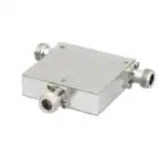 RF Circulators
 Coaxial RF Power Dividers
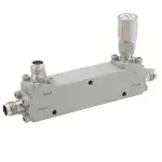 RF Couplers
 RF Filters
Directivity is the most overlooked parameter in directional coupler selection, yet it has the greatest impact on measurement accuracy. Directivity = Isolation – Coupling — the three values are interrelated, not independent. Insufficient directivity causes significant reading errors in base-station power monitoring and radar return-loss measurement. ZOMWAVE RF directional couplers cover DC–40 GHz with typical directivity ≥20 dB. Standard products ship in 5 business days; OEM parameter customization is available.
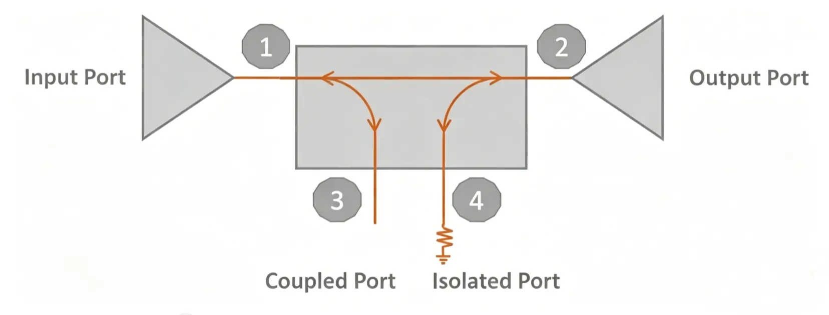
1.Four Ports, Two Core Parameters
An RF directional coupler is a four-port passive device. Signal flows in one direction: Port 1 (input) → Port 2 (through), while a fraction of energy is extracted to Port 3 (coupled). Port 4 (isolated) ideally receives zero output.
Coupling (C) the ratio, in dB, of input power to coupled-port power. Larger coupling = less sampled energy. Typical range: 3 dB (equal split) to 40 dB (trace sampling). Coupling is a design intent: choose based on how much signal the detector or feedback loop requires.
Directivity (D) the ability to distinguish forward signal from reverse leakage. D = Isolation − Coupling. Higher directivity means the coupled port sees a purer forward signal with less reverse contamination.
2.Low Directivity Means Unreliable Power Monitoring
PA output-power calibration in base stations is the most common application for directional couplers. The coupled port connects to a detector or power meter that reads forward power in real time. When directivity is insufficient, reflected energy from the antenna or load leaks into the coupled port. The detector reads the sum of forward signal and reverse leakage—not the true forward power.
Directivity | Reverse Leakage (refl. −15 dBm) | Forward Signal (30 dBm input) | Monitoring Error |
15 dB | −30 dBm | −10 dBm (C = 40 dB) | 0.05 dB |
15 dB | −30 dBm | 0 dBm (C = 30 dB) | 0.04 dB |
10 dB | −25 dBm | −10 dBm | 0.28 dB |
10 dB | −25 dBm | 0 dBm | 0.41 dB |
Key takeaway: when coupling is large (weak coupled-port signal) and reflections are strong, the impact of low directivity is amplified. 5G macro-base-station power monitoring requires accuracy within ±0.5 dB; radar return-loss measurement demands directivity ≥25 dB. Always verify with worst-case conditions—maximum reflection combined with minimum coupled signal.
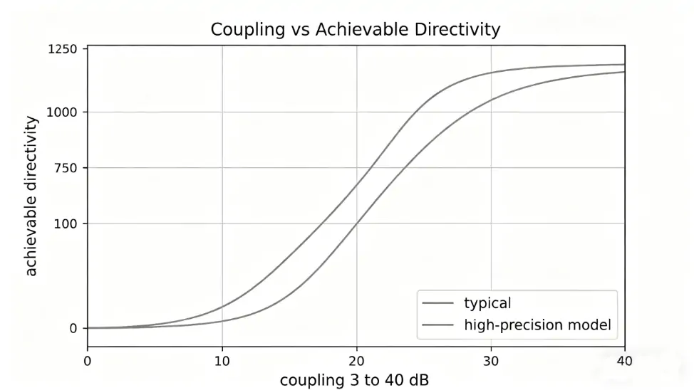
3.The Trade-Off Between Coupling and Directivity
Coupling and directivity are not independent. They share the same coupling structure, so one constrains the other physically.
Tight coupling (3–10 dB): directivity of ≥20 dB is relatively easy to achieve because the coupling path is strong and manufacturing tolerances have less impact on phase balance. The cost is higher insertion loss on the main path (theoretical minimum equals the power-splitting loss), unacceptable for link-budget-sensitive systems.
Loose coupling (20–40 dB): directivity becomes the real challenge. A 30 dB coupling means the coupled-port signal is 1000× weaker than the main path. Any minor machining deviation, dielectric inhomogeneity, or port mismatch increases reverse leakage. Achieving ≥20 dB at this level demands extreme cavity-machining precision and material consistency.
Coupling | Typical Directivity | High-Precision Directivity | Theoretical Min. Insertion Loss |
3 dB | 20–25 dB | ≥30 dB | 3.0 dB |
6 dB | 20–25 dB | ≥28 dB | 1.3 dB |
10 dB | 18–23 dB | ≥25 dB | 0.46 dB |
20 dB | 15–20 dB | ≥22 dB | 0.04 dB |
30 dB | 12–18 dB | ≥20 dB | 0.004 dB |
Selection logic: determine coupling based on how much monitoring the system needs, then pick the highest directivity available within budget. Actual numbers depend on the manufacturer’s cavity design and manufacturing process.
4.How Frequency Drift Degrades Directivity
Parameters of wideband couplers (bandwidth ratio > 1.5:1) are all frequency dependent. Datasheet directivity is typically the mid-band typical value; edge-of-band performance degrades.
Root cause: the electrical length of the coupling region shifts with frequency. When the operating frequency deviates from the design center frequency, the phase balance between forward and reverse signals breaks down, isolation drops, and directivity follows. Typical degradation: 3–8 dB lower at band edges compared to mid-band.
Temperature compounds this. Dielectric constant drift over −45°C to +85°C changes the effective electrical length. Across the full temperature range, directivity can shift by ±2–3 dB.
Design checklist: verify at three worst-case corners—highest frequency + highest temperature; lowest frequency + lowest temperature; band edge + nominal temperature. If the worst corner passes the system requirement, other conditions will not be the limiting factor.
5.VSWR and Termination Matching: The Hidden Directivity Killer
The isolated port (Port 4) termination quality directly affects directivity. Ideally Port 4 connects to a matched 50Ω load that absorbs all leaked energy. Two failure modes:
Port 4 termination mismatch: if the termination VSWR degrades from 1.05 to 1.50, reflected energy back to the main line increases. Effective directivity drops by 5–10 dB. Engineers often overlook this during system integration.
Port 4 termination power rating: although Port 4 absorbs only a fraction of main-path power, under extreme conditions (high main-path reflection + low coupling), the absorbed power can exceed the termination resistor rating. When the resistor burns out and opens, all energy reflects back to the main line—directivity drops to zero, main-path VSWR deteriorates catastrophically, potentially damaging upstream components.
Design rule: select the termination resistor rated at 2× the maximum power Port 4 could absorb. Check connector torque during installation. In high-power and high-temperature environments, prefer internally matched three-port configurations that eliminate the external termination as a point of failure.
6.Major Brand Comparison
1.ZOMWAVE: DC–40 GHz coverage, typical directivity ≥20 dB, N-type and SMA connectors available. Standard products ship in 5 business days; OEM customization of coupling, directivity, and frequency range is supported. Best fit for delivery-sensitive projects and batch orders requiring non-standard parameters.
2.Mini-Circuits: full broadband product line from HF to 40 GHz. Specs are transparent and S-parameter files are downloadable for ADS/HFSS simulation. Preferred choice for R&D and lab environments.
3.Pasternack: deep inventory and practical web-based parametric search tools accelerate selection. Suitable for fast-prototyping verification and small-volume procurement.
4.Marki Microwave: technical expertise in narrowband high-directivity designs; some models achieve 30+ dB directivity. Appropriate for precision measurement and VNA applications.
5.KMW (Korea): competitive pricing for volume production. Viable option for cost-sensitive projects where parameters fall within the standard range.
6.Selection summary: R&D prototyping → Mini-Circuits (transparent specs, simulation-ready); volume production → ZOMWAVE (fast delivery, customizable); extreme precision requirements → Marki; budget-constrained volume → KMW.
7.Frequently Asked Questions
Q: Is 20 dB directivity sufficient?
A: Depends on the application. Power monitoring generally works with 15–20 dB; VSWR measurement typically requires ≥25 dB; network-analyzer calibration standards demand ≥35 dB. Approximate error from directivity: ±(reverse signal level − directivity). The larger the reflection in your system, the higher the directivity required.
Q: What is the fundamental difference between a 3 dB and a 30 dB directional coupler?
A: A 3 dB unit is used as a power splitter/combiner—two paths with equal power, focusing on amplitude balance and phase consistency. A 30 dB unit is a signal sample extracting a tiny fraction of main-path power for monitoring or feedback. Their design constraints are completely different.
Q: What are the advantages of a dual-directional coupler over a single-directional coupler?
A: A dual-directional coupler provides both forward and reverse coupled ports simultaneously. This allows real-time monitoring of transmitted power and reflected power, enabling direct VSWR and return-loss calculation. Single-directional couplers measure only one direction. PA monitoring and antenna feed-line monitoring in base stations typically require dual-directional units.
Q: How do I measure directivity? What equipment is needed?
A: A vector network analyzer (VNA) is required. Method: measure coupling (Port 1 → Port 3, expressed as C in dB), then measure isolation (Port 3 → Port 1, expressed as I in dB). Directivity = I − C. Calibrate the VNA before testing. Ensure that the test cables and connectors themselves have directivity higher than the device under test; otherwise, the measurement result is invalid.