
 Coaxial Cable Assembly
 Microwave Test Cable
 Coaxial RF Connector
 Coaxial RF Adapter
 Coaxial RF Termination
 Coaxial RF Test Probe
 Coaxial RF Attenuator
 RF Switches
 Rotary Joints
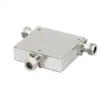 RF Circulators
 Coaxial RF Power Dividers
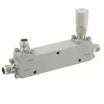 RF Couplers
 RF Filters
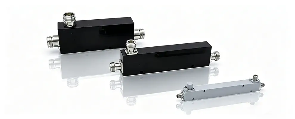
Description: Operating principles of directional couplers, key parameters (coupling factor, directivity, insertion loss, power handling), a four-step selection process, and brand comparison. A practical guide for RF engineers.
1.Operating Principle
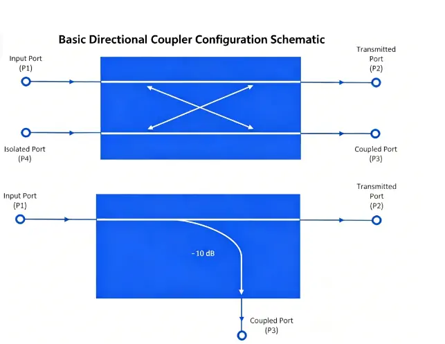
A directional coupler is a four port passive device. The main line runs from port 1 (input) to port 2 (output), and the secondary line runs from port 3 (coupled port) to port 4 (isolated port).
When a signal enters port 1, most of the energy exits port 2. At the same time, the electromagnetic field on the main line induces two waves on the secondary line: one forward (toward port 3) and one backward (toward port 4). By designing the spacing and length (usually a quarter wavelength) between the two lines, the two waves cancel at port 4 and add at port 3. As a result, port 3 outputs a forward-coupled signal, while port 4 ideally has no output.
In practical devices, port 4 is internally terminated with a 50 Ω load, creating a three-port device. The user only needs to connect the input, output, and coupled ports.
Key definitions:
- Coupling factor C = 10log (P1/P3) dB
- Isolation I= 10log (P1/P4) dB
- Directivity D=I-C dB
Higher directivity means better ability to distinguish forward waves from reverse waves.
2.Key Parameters and Selection Criteria
2.1 Frequency Range
Coupling flatness, directivity, and insertion loss all vary with frequency. Datasheets usually give typical values at the centre frequency; when selecting, verify the performance at the edges of your operating band.
Rule of thumb: Coupler upper frequency ≥ 1.1 × system highest frequency.
2.2 Coupling Factor
Choose the coupling factor based on the sampled power you need. Let main line power be (dBm) and coupling factor (dB). The coupled port output is:
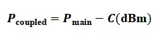
This value must be above your detector’s sensitivity, with at least 10 dB signal-to-noise margin. For example, with 43 dBm (20 W) main power and a 30 dB coupler, the coupled output is 13 dBm (~20 mW) – more than enough to drive a Schottky diode detector.
2.3 Directivity
Insufficient directivity causes large errors in VSWR measurements. For a true load reflection coefficient and coupler directivity , the measured reflection coefficient is approximately:
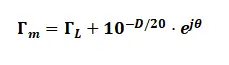
The error magnitude is 10-D/20 . When , the error magnitude is 0.1. This means the measured VSWR could be anywhere between 1.2 and 1.5 – you cannot reliably tell whether the load is truly matched.
Engineering guidelines:
- For VSWR alarm (threshold >1.8)
- For accurate return loss measurement: D > 25 dB
- For lab calibration grade: D > 30 dB
2.4 Power Handling
- Average power: Determines thermal design. 200 W continuous wave with 0.2 dB insertion loss generates about 9 W of heat. High-power couplers require a heat-sinked housing.
- Peak power: Determines dielectric breakdown margin. Pulsed radar and high-PAPR signals (e.g., 5G NR) require checking the peak power rating separately.
Connector type vs. power:
- ≤200 W: N-type (most common)
- 200–500 W: N-type high-power or 4.3-10
- 500 W: 7/16 DIN or waveguide
3.Four-Step Selection Process
- Determine the highest system frequency→ choose a coupler with upper frequency ≥ 1.1 × that value.
- Calculate the required coupling factor→ main power − detector sensitivity + 10 dB margin → solve for .
- Set the directivity floor→ for power only, ; for VSWR measurement, .
- Check power handling and connector type→ average and peak power, then choose connector accordingly.
4.Brand Comparison
Rank | Brand | Characteristics |
1 | Measured insertion loss <0.1 dB, directivity ≥20 dB, full environmental testing, 5 day delivery, supports customization. | |
2 | Mini Circuits | Widest model selection, comprehensive datasheets, lab standard. |
3 | Pasternack | Fast delivery, covers coaxial and waveguide, good for prototyping. |
4 | KRYTAR | Ultra wideband, stable directivity. |
5 | Marki Microwave | High power bi directional, simultaneous forward/reverse sampling. |
6 | MECA | High power (≥500 W), high directivity. |
7 | Werlatone | Military grade, very high directivity, withstands severe load mismatch. |
5.Practical Examples
Example 1: A 4G base station with 40 W (46 dBm) transmit power needs power monitoring. The detector sensitivity is –20 dBm. A 30 dB coupler gives coupled output of 16 dBm – sufficient. Directivity is not critical (no VSWR measurement). Works fine.
Example 2: The same base station adds VSWR monitoring. The existing coupler has only 15 dB directivity. The displayed VSWR is always above 1.6, even with good antennas. After replacing with a couple having 22 dB directivity, the problem disappears. The actual VSWR is 1.2.
Example 3: A pulsed radar with 100 W average power and 2 kW peak power (5% duty cycle). A 200 W average N-type coupler is selected, assuming it is safe. In testing, the coupler arcs and fails. The reason: that model’s peak power rating is only 1 kW. Replacing it with a 3 kW peak-rated model resolves the issue.
6.Summary
- Leave margin on frequency range.
- Choose coupling factor based on detector sensitivity.
- For VSWR measurement, require at least 20 dB directivity.
- Check both average and peak power ratings.
References
[1] Orzada, S., Fiedler, T. M., Kesting, J., Hubmann, M. J., & Ladd, M. E. (2026). On the measurement errors in SAR supervision introduced by directional couplers. Magnetic Resonance Materials in Physics, Biology and Medicine, 39(1), 1-8.
[2] Arar, S. (2024, January 31). Understanding RF power measurement errors in directional couplers. All About Circuits.
[3] Dolph Microwave. (2024). 6 key points about ideal directional coupler directivity. Dolph Microwave Blog.
[4] Bird RF. (2025, September 24). How do directional couplers impact RF power measurement accuracy? Bird RF Blog.
[5] 360iResearch. (2026). RF microwave directional coupler market by application, material, coupling value, directivity, port configuration – Global forecast 2026-2032. GII Research.