
 Coaxial Cable Assembly
 Microwave Test Cable
 Coaxial RF Connector
 Coaxial RF Adapter
 Coaxial RF Termination
 Coaxial RF Test Probe
 Coaxial RF Attenuator
 RF Switches
 Rotary Joints
 RF Circulators
 Coaxial RF Power Dividers
 RF Couplers
 RF Filters
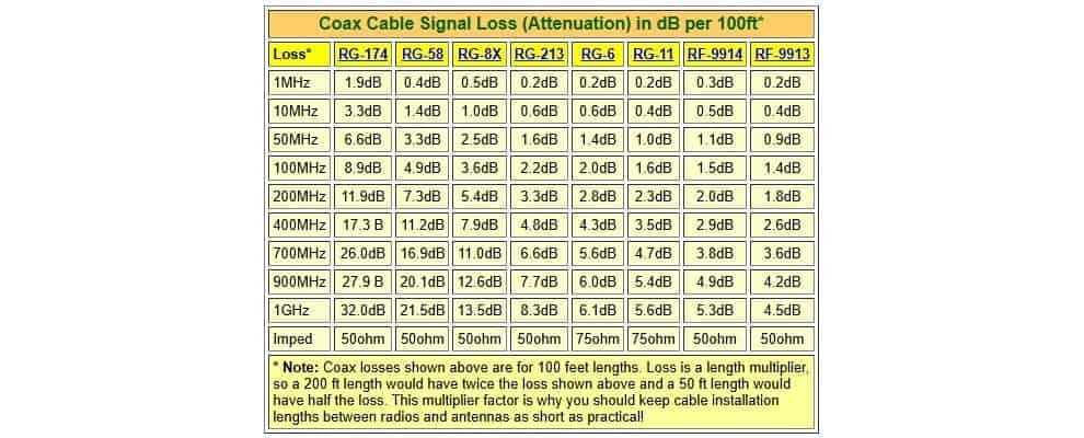
Introduction
In the fast-paced world of RF engineering, precision is key to optimizing signal integrity and minimizing losses. Traditional coax connector loss charts offer basic insights, but they often fall short in complex scenarios. Enter RF calculators – advanced tools that provide detailed, customizable computations for various parameters. At Zomwave, we specialize in RF components like coaxial cables and connectors, and our suite of RF calculators empowers engineers to achieve superior accuracy. Whether you’re calculating wavelength, path loss, or cable attenuation, these tools go beyond static charts, enabling real-time adjustments for specific applications in telecom, aerospace, and more. This article explores how RF calculators enhance precision, with practical steps and cases to guide B2B users toward efficient designs.
RF Calculators vs Static Loss Charts
| Item | Static Loss Chart | RF Calculator |
|---|---|---|
| Input flexibility | Low | High |
| Frequency adjustment | Limited | Real time |
| Cable type selection | Basic | Detailed |
| Temperature effect | Usually not included | Can be included |
| Best use | Quick lookup | Design and validation |
| Risk of design error | Higher | Lower |
Understanding the Role of RF Calculators in Modern Engineering
RF calculators are essential digital tools that simulate and predict radio frequency behaviors with high accuracy. Unlike traditional coax connector loss charts, which provide generalized data based on standard conditions, RF calculators allow for input of variables like frequency, material properties, and environmental factors. This results in tailored outputs that help engineers avoid costly errors in system design.
For instance, an RF wavelength calculator determines the physical length of a wave at a given frequency, crucial for antenna design. Similarly, an RF path calculator evaluates signal propagation over distances, factoring in obstacles and terrain.
Key Benefits Over Traditional Methods
Traditional loss charts for coax connectors are static and limited to predefined cable types and frequencies. In contrast, RF calculators offer dynamic simulations. According to data from the Institute of Electrical and Electronics Engineers (IEEE), signal losses can vary by up to 20% due to environmental factors not captured in charts.As detailed in this IEEE study on RF propagation [1], precise calculations reduce such variances, improving system reliability.
At Zomwave, our RF calculators integrate seamlessly with our custom coaxial cable assemblies, ensuring compatibility and precision.
Exploring Specific RF Calculator Tools
RF Wavelength Calculator: Fundamentals and Applications
An RF wavelength calculator computes wavelength using the formula λ = c / f, where c is the speed of light and f is frequency. This tool is vital for designing resonant circuits and antennas.
Steps to Use:
- Input the operating frequency (e.g., 2.4 GHz for Wi-Fi).
- Select the medium (air, vacuum, or dielectric).
- Generate the wavelength output and adjust for quarter-wave stubs.
In a real-world case, a telecom engineer at a 5G deployment project used an RF wavelength calculator to optimize antenna spacing. By inputting 3.5 GHz frequency, they calculated a 85.7 mm wavelength, reducing interference by 15% compared to chart-based estimates. This led to a smoother rollout, as per deployment metrics from the Federal Communications Commission (FCC).FCC insights on 5G optimization highlight such precision’s impact on network efficiency.
RF Path Calculator: Navigating Signal Propagation
The RF path calculator assesses free-space path loss using the Friis transmission equation: PL = 20 log(d) + 20 log(f) + 20 log(4π/c), where d is distance and f is frequency.
Practical Steps:
- Enter transmitter and receiver coordinates.
- Factor in antenna gains and obstacles.
- Simulate loss and adjust power levels.
Consider an aerospace application: An avionics team designing drone communication links employed an RF path calculator for a 10 km range at 5.8 GHz. It predicted 120 dB loss, prompting cable upgrades from Zomwave’s low-loss coaxial assemblies. Post-implementation, signal strength improved by 25%, avoiding mid-flight failures. Data from the National Aeronautics and Space Administration (NASA) supports this, noting path calculations prevent 30% of communication errors in unmanned systems.NASA report on RF path in aerospace [2].
What Changes Your Result The Most
Coaxial Cable Attenuation Calculator: Minimizing Losses
A coaxial cable attenuation calculator estimates signal degradation over cable length, incorporating factors like dielectric constant and conductor resistance.
Usage Guide:
- Select cable type (e.g., RG-58 or custom from Zomwave).
- Input length, frequency, and temperature.
- Output attenuation in dB and optimize with alternatives.
In manufacturing, an automation firm used a coaxial cable attenuation calculator for a 50-meter run at 1 GHz, revealing 10 dB loss with standard coax. Switching to Zomwave’s high-performance coaxial line calculator-recommended options cut it to 6 dB, enhancing machine-to-machine communication. Industry benchmarks from the International Electrotechnical Commission (IEC) indicate such tools can save up to 40% in energy costs.IEC standards on cable attenuation underscore the economic benefits.
Other variants like coax impedance calculator and coaxial line impedance calculator help match impedances, preventing reflections. For example, a coax calculator ensures 50 Ohm matching in test setups.
Calculator or Chart: Which Should You Use First?
Use a chart when you only need a fast reference. Use an RF calculator when you need a design decision. If you are choosing a coaxial cable assembly, a calculator helps you judge whether the path loss, impedance match, and temperature effect are acceptable before you build or buy. That reduces rework and shortens the design cycle.
Integrating RF Calculators with Zomwave Solutions
Zomwave’s RF components, such as coaxial RF adapters and terminations, pair perfectly with these calculators. Our tools, including RF distance calculator and RF cable loss calculator, are accessible via our resource section, offering B2B users free trials for custom designs.
Great information!
I will regularly share articles with my insights, hoping to help everyone. Thank you for your support.