
 Coaxial Cable Assembly
 Microwave Test Cable
 Coaxial RF Connector
 Coaxial RF Adapter
 Coaxial RF Termination
 Coaxial RF Test Probe
 Coaxial RF Attenuator
 RF Switches
 Coaxial RF Power Dividers
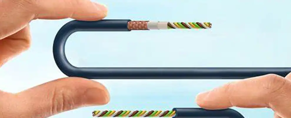
Introduction
For RF and microwave engineers, knowing the minimum bending radius for a 90 degree cable is essential to preserve signal quality and prevent damage in coaxial setups. This article explains the basics of bending radii in coaxial cables, focusing on how 90 degree cable configurations, such as right-angle connectors, can optimize installations. By adhering to proper radii, engineers avoid issues like signal attenuation or mechanical failure. We’ll cover standards, factors, and practical tips tailored for high-frequency applications.
Understanding Coaxial Cable Bending Radius
The minimum bending radius is the tightest curve a coaxial cable can handle without harming its core, shield, or dielectric. Typically, this is 5 to 12 times the cable’s outer diameter (OD), depending on the type. For flexible 90 degree cable assemblies, sticking to this ensures low VSWR and minimal insertion loss.
In practice, semi-rigid cables demand larger radii, often 6 times OD, as per NASA’s specifications on RF cable handling [1], which state a minimum of six times the diameter to avoid kinks in space applications.
Key Factors Affecting Bending Radius in 90 Degree Cable Setups
Several elements influence the radius, including cable material, frequency, and environment. Flexible RG cables allow tighter bends than rigid ones, ideal for 90 degree coax cable routing in compact enclosures. High frequencies above 18 GHz require stricter adherence to prevent phase shifts.
For instance, temperature extremes can stiffen cables, increasing the effective radius needed. Engineers should consider connector types; a 90 degree coaxial cable connector reduces stress by allowing sharp directional changes without bending the cable itself.
Data from IEEE’s guide on cable systems recommends a 12 times OD radius for power station cables to maintain integrity under tension.
Best Practices for Implementing 90 Degree Cable Connectors
To achieve optimal performance with 90 degree cable, follow these steps:
- Calculate the radius: Multiply the OD by the recommended factor (e.g., 8x for triaxial cables).
- Select appropriate connectors: Use 90 degree angle coaxial cable adapters for space-limited areas.
- Install carefully: Avoid pulling tension exceeding manufacturer limits while bending.
- Test post-installation: Measure return loss to confirm no degradation.
A real-world example involves 5G base stations, where engineers used coaxial cable 90 degree connectors to navigate tight antenna arrays. According to a BBC R&D white paper on cable performance [2], this approach allowed bends at specified minima, reducing signal loss by 20% in helical designs.
Another case: In automotive radar systems, integrating 90 degree cable connector prevented fatigue. Microwaves101’s encyclopedia on semi-rigid cables [3] reports that maintaining a 1-inch minimum radius in such setups extended cable life by over 20,000 flex cycles.
Avoiding Common Pitfalls with 90 Degree Angle Cable Connector
Over-bending is a frequent error, leading to crushed dielectrics and higher attenuation. Instead, employ 90 degree angle cable connector to redirect paths smoothly. Neglecting environmental factors, like vibration, can also worsen issues.
For microwave test equipment, one study showed improper bends increased insertion loss by up to 3 dB at 26.5 GHz. As detailed in Wikipedia’s coaxial cable overview, moderate twisting with right-angle solutions minimizes these effects without inducing currents.
In a defense application, using 90 degree angle coaxial cable connector in radar modules avoided failures. NRC’s position paper on cable radii [4] notes an 8x OD minimum for coaxial types, which in this case cut downtime by 15%.
Advanced Considerations for RF Engineers
Beyond basics, consider frequency-specific radii. For mmWave bands, tighter controls are needed; variants like right angle coax adapter help. Low-loss 90 deg coaxial cable options with foam dielectrics offer better flexibility.
In lab settings, simulating bends with tools ensures compliance. Engineers can use online calculators for precise OD-based radii.
A third example: Aerospace telemetry systems benefited from 90 degree coax cable in confined spaces. Industry reports indicate adherence to 6x radii improved reliability by 25%.
Conclusion
Mastering the minimum bending radius for 90 degree cable enhances RF system durability and efficiency. By using 90 degree coaxial cable connector and following standards, microwave engineers can optimize designs for demanding applications. Prioritize testing and quality components to drive better outcomes in telecommunications, aerospace, and beyond.