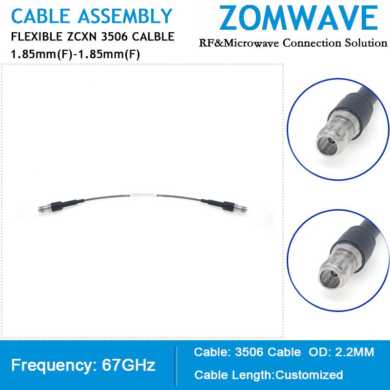
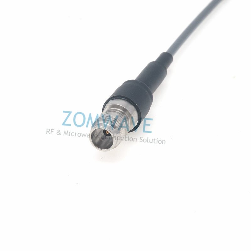
RF coaxial cables 2.4mm Male to 2.4mm Female ZCXN 3507 cable assemblies are part of the largest coaxial cable selection for RF, microwave and millimeter wave interconnect solutions. ZOMWAVE coaxial cable assembly products are used for high-quality applications, such as laboratory radio frequency testing and measurement. They are sturdy and durable. They are designed for aerospace, radar, microwave, test system, etc. 2.4mm Male to 2.4mm Female cable assembly is constructed with ZCXN 3507, which is a flexible type of coaxial cable with high phase and amplitude stability. The flexible 2.4mm cable assembly is manufactured with 2.4mm Stainless Steel connectors, with 50 ohm impedance and triple shielding coaxial cable. ZOMWAVE is the place to buy high-quality 2.4mm Male to 2.4mm Female cable assemblies, which can be shipped quickly worldwide. Variations of 2.4mm cable assemblies can also be manufactured and will be shipped within 5 days.

 Coaxial Cable Assembly
 Microwave Test Cable
 Coaxial RF Connector
 Coaxial RF Adapter
 Coaxial RF Termination
 Coaxial RF Test Probe
 Coaxial RF Attenuator
 RF Switches
 Rotary Joints
 Coaxial RF Power Dividers
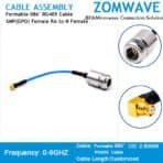
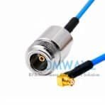
 Female Right Angle to NType Female, Formable .086_ RG405Cable, 6GHz")
 Female Right Angle to NType Female, Formable .086_ RG405Cable, 6GHz(1)")