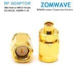
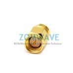
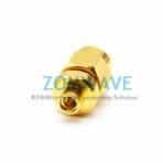
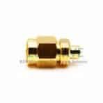
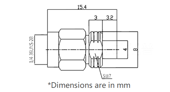
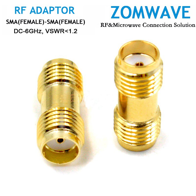
ZOMWAVE supplies a waterproof SMA female to SMA female bulkhead adapter designed for straightforward alignment and routing in 50 ohm networks, offered in a 24 mm straight body length and rated to 6 GHz with VSWR less than or equal to 1.2 and insertion loss at or below 0.05 times the square root of frequency in GHz. Constructed from brass with nickel underplate and gold plating, the adapter withstands harsh conditions with MIL STD qualified performance for vibration, shock, thermal shock, moisture, and salt spray, and endures more than 500 mating cycles while simplifying panel installations and reducing assembly time. Shipped with traceable test reports and in-house testing, and available for fast turnaround with 5-day shipping out, this SMA female to SMA female bulkhead adapter lowers total cost of ownership by standardizing parts to cut inventory complexity, enabling easier field replacement and maintenance, and supports high-frequency assemblies, test benches, and subsystem interconnects where reliable, low insertion loss, and mechanical tolerance are critical.
 Coaxial Cable Assembly
 Microwave Test Cable
 Coaxial RF Connector
 Coaxial RF Adapter
 Coaxial RF Termination
 Coaxial RF Test Probe
 Coaxial RF Attenuator
 RF Switches
 Rotary Joints
 RF Circulators
 Coaxial RF Power Dividers
 RF Couplers
 RF Filters
")
")
")