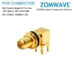
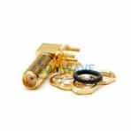
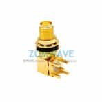
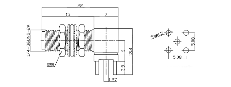
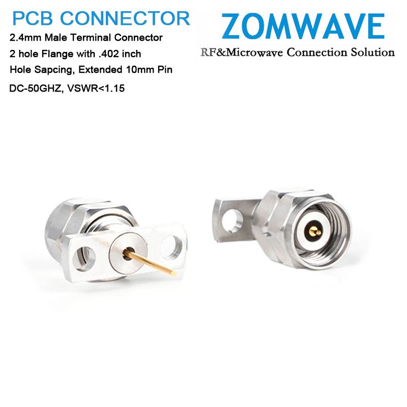
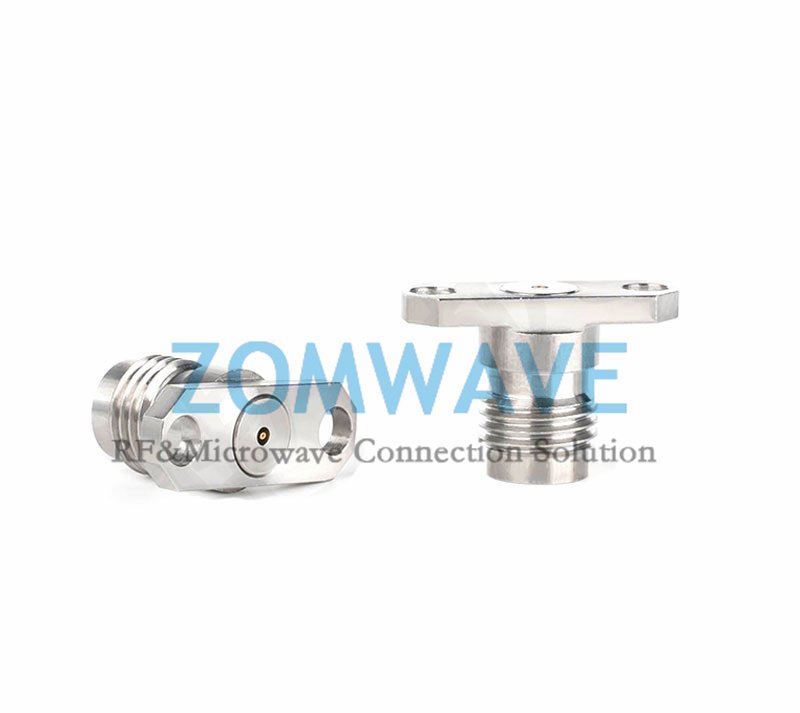
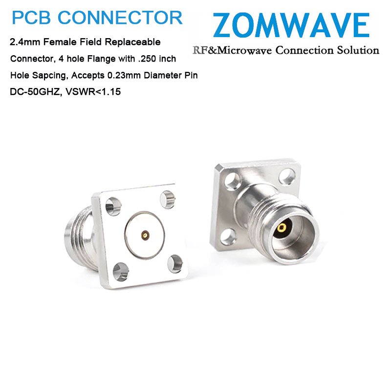
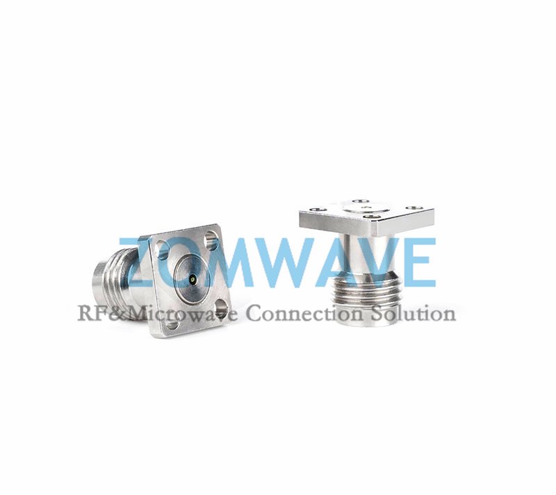
ZOMWAVE offers 5-day shipping with negotiated pricing for its SMA Female Bulkhead RA Thru Hole PCB Connector, delivering production-ready RF interfaces for procurement and manufacturing teams. This connector features precise sma bulkhead connector dimensions of .201 inch x .051 inch thru hole interface and maintains 50 Ohm impedance, utilizing shield and contact solder attachment for reliable mechanical and electrical connections. Critical sma female dimensions ensure proper PCB fitment while covering DC to 12 GHz with PTFE dielectric and typical VSWR of 1.25. The brass body features gold plating with beryllium copper contacts for lasting conductivity and corrosion resistance. RoHS and REACH compliant, this SMA female connector is stocked among 40,000+ RF components for global shipment and is compatible exclusively with 2.4mm interfaces. ZOMWAVE also provides SMA Female Straight Thru Hole PCB Connectors and broader sma female bulkhead connector options, including assemblies designed for sma connector bulkhead solder applications. These solutions simplify PCB mounting processes while ensuring mechanical traceability and testable performance. Ideal for sma to sma bulkhead connector implementations, this connector eliminates installation errors through standardized sma bulkhead connector dimensions, reduces rework with consistent solder fillets and inspection points, and streamlines volume production with full documentation and IQC-friendly testing protocols.
Key specifications
| Configuration | |
| Connector Series | SMA |
| Connector Gender | Female |
| Connector Angle | Right Angle |
| Connector Mount Method | Bulkhead |
| Attachment Method | Solder |
| Interface Type | Thru Hole |
| Material | |
| Centre Contact | Berylium-copper, gold plated |
| Body | Brass, gold plated |
| Insulators | PTFE |
| Electrical Specifications | |
| Impedance | 50 ohm |
| Frequency Range(From DC) | 12GHZ |
| VSWR | ≤1.25:1 (DC 0~12GHz) |
| Insertion Loss | 0.05 xSqt.(f_Ghz) |
| Voltage Rating | 150 V(rms) |
| Dielectric Withstanding Voltage | 500 V |
| Insulation Resistance | ≥500 Mohm |
| Mechanical Characteristics | |
| Mating Cycles | ≥ 500 cycles |
| Mating Torque | 5-7 in - lbs |
| Environmental Characteristics (RoHS Complliant) | |
| Temperature Rating | -40°C ~ +125°C |
| Corrosion (Salt Spray) | MIL-STD-202, Method 101, Condition B |
| Vibration | MIL-STD-202, Method 204, Condition D, 20 Gs |
| Shock | MIL-STD-202, Method 213, Condition I, 100 Gs |
| Thermal Shock | MIL-STD-202, Method 107. Cond. B, -40°C to +85°C |
| Moisture Resistance | MIL-STD-202, Method 106, Less Step 7B |
| Barometric Pressure (Altitude) | MIL-STD-202, Method 105, Condition C, 70k Ft |
CAD Drawing
Dimensions in mm/ [inch], Tolerance +1%
Coaxial Cable Assembly
Microwave Test Cable
Coaxial RF Connector
Coaxial RF Adapter
Coaxial RF Termination
Coaxial RF Test Probe
Coaxial RF Attenuator
RF Switches
Coaxial RF Power Dividers