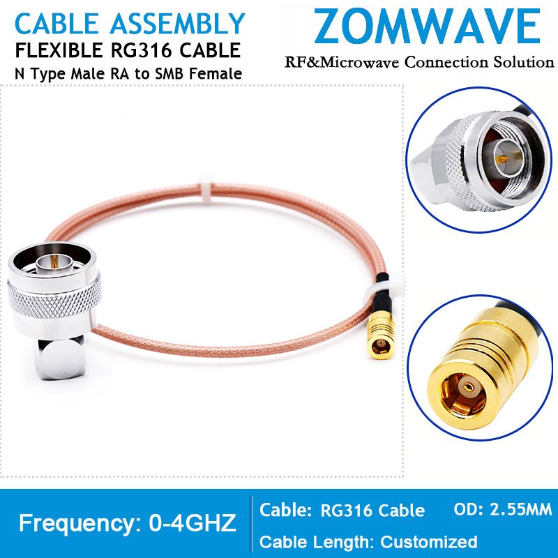
ZOMWAVE provides a reliable N Type Male Right Angle to SMB Female cable assembly, designed for precision in demanding applications. This smb female n male cable is constructed using high-quality RG316 flexible cable, offering exceptional performance within a compact form factor. The 50-ohm N type cable assembly incorporates a PTFE dielectric and FEP jacket, ensuring stable, low-loss signal transmission up to 4 GHz. The assembly’s advanced construction includes a silver-plated copper-clad steel center conductor, a tin-coated copper braid shield, and nickel-plated brass coupling hardware, all providing secure connections, minimal contact resistance, and reduced signal leakage. This design ensures consistent impedance and minimizes intermodulation distortion, essential for critical applications in industries such as automotive, 5G, military, quantum computing, and medical systems. ZOMWAVE’s offering includes no minimum order quantity (MOQ), five-day shipping, and 100% functional testing, enabling system integrators to streamline prototyping, reduce downtime, and meet rigorous environmental requirements. The product also supports rapid customization of various lengths, with detailed production test reports to expedite validation, cut integration time, and reduce overall costs.
Key specifications
| Configuration | |
| Connector Series 1 | Type N |
| Connector Gender 1 | Male |
| Connector Angle 1 | Right Angle |
| Connector Mount Method1 | None |
| Body Materials and Plating 1 | Brass, Nickel Plated |
| Connector Series 2 | SMB |
| Connector Gender 2 | Female |
| Connector Angle 2 | Straight |
| Connector Mount Method 2 | None |
| Body Materials and Plating 2 | Brass, Nickel Plated |
| Cable Type | RG316 |
| Electric Specifications | |
| Impedance | 50ohm |
| Frequency Range(From DC) | 4GHz |
| VSWR | ≤1.35:1 (DC 0~4GHz) |
| Insertion Loss | Depends on cable length |
| Voltage Rating | 335 V(rms) |
| Dielectric Withstanding Voltage | 500 V |
| Insulation Resistance | ≥500 Mohm |
| Mechanical Characteristics | |
| Mating Cycles | ≥ 500 cycles |
| Mating Torque | 30 in - lbs |
| Environmental Characteristics (RoHS Complliant) | |
| Temperature Rating | -40°C ~ +85°C |
| Corrosion (Salt Spray) | MIL-STD-202, Method 101, Condition B |
| Vibration | MIL-STD-202, Method 204, Condition D, 20 Gs |
| Shock | MIL-STD-202, Method 213, Condition I, 100 Gs |
| Thermal Shock | MIL-STD-202, Method 107. Cond. B, -40°C to +85°C |
| Moisture Resistance | MIL-STD-202, Method 106, Less Step 7B |
| Barometric Pressure (Altitude) | MIL-STD-202, Method 105, Condition C, 70k Ft. |
| Cable Specification | |
| Center Conductor | Silver plated copper |
| Dielectric | PTFE |
| Jacket | FEP |
| Jacket Diameter(mm) | 2.50±0.05 |
| Min. Bending Radius(mm) | 15 |
| Shielding Effect(dB) | >80 |
| Weight(kg/km) | 16 (Reference) |
| Coaxial Cable Attenuation @ 20℃ and Sea Level, Power | |
| Frequency (GHz) | Attenuation(dB/m) |
| 0.1 | 0.29 |
| 0.4 | 0.58 |
| 0.9 | 0.88 |
| 1 | 0.93 |
| 1.8 | 1.27 |
| 2.4 | 1.46 |
| 3 | 1.65 |
| 5 | 2.14 |
| 6 | 2.34 |

 Coaxial Cable Assembly
 Microwave Test Cable
 Coaxial RF Connector
 Coaxial RF Adapter
 Coaxial RF Termination
 Coaxial RF Test Probe
 Coaxial RF Attenuator
 RF Switches
 Coaxial RF Power Dividers


