
 Coaxial Cable Assembly
 Microwave Test Cable
 Coaxial RF Connector
 Coaxial RF Adapter
 Coaxial RF Termination
 Coaxial RF Test Probe
 Coaxial RF Attenuator
 RF Switches
 Rotary Joints
 Coaxial RF Power Dividers
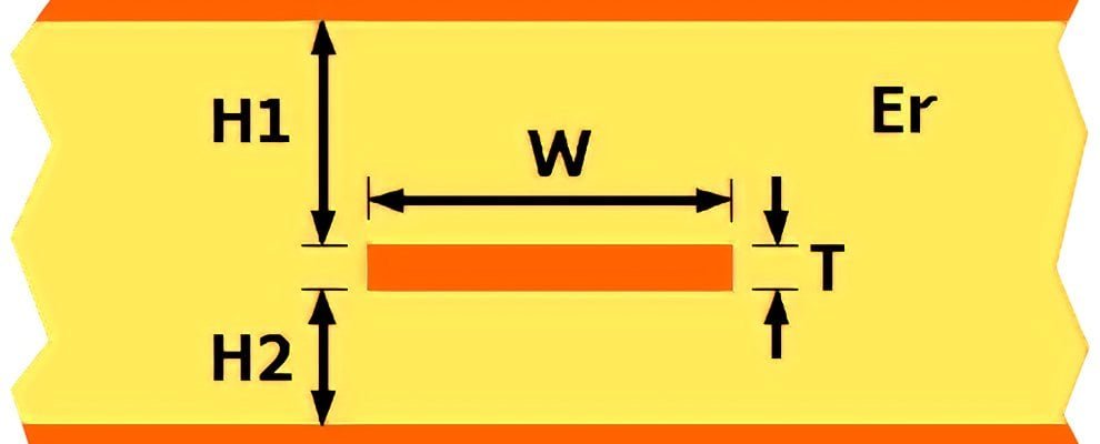
In high-frequency circuit design, calculating stripline impedance is vital for signal integrity and circuit matching. A strip line calculator impedance tool can streamline this, but understanding the process ensures better control over your designs. This article explores the problem of determining stripline impedance in ohms, analyzes the influencing factors, and provides a clear solution with a practical example, tailored for B-end users seeking reliable PCB solutions.
The Problem: Why Calculate Stripline Impedance?
Ensure signal integrity in microwave circuits and PCBs with our precision impedance calculator stripline, essential for preventing reflections and circuit failure. This specialized tool addresses the unique demands of planar transmission lines, distinct from coaxial approaches. RF engineers and PCB designers rely on it for accurate stripline Z calculation to perfectly match antennas, filters, and critical components. Achieve reliable performance by precisely determining stripline impedance parameters vital for high-frequency design success.

Analyzing the Factors
Stripline impedance depends on several parameters:
Dielectric Constant (ε_r)
The dielectric material’s relative permittivity impacts signal speed. A higher ε_r reduces impedance, common in materials like FR4 (ε_r ≈ 4.5).
Conductor Width (W)
Wider conductors lower impedance, offering more current-carrying capacity, while narrow ones increase it, suiting compact designs.
Dielectric Height (H)
The spacing between the conductor and ground planes. Greater H decreases impedance, affecting signal propagation.
Conductor Thickness (T)
Typically negligible in thin conductors, thicker ones slightly adjust impedance, critical in high-power applications.
Unlike coaxial cables—where a coaxial cable calculator uses dimensions like inner and outer diameters—striplines rely on planar geometry, making their impedance unique.
Solving the Problem: The Stripline Impedance Formula
The standard stripline impedance formula for thin conductors is:
[ Z = \frac{60}{\sqrt{\epsilon_r}} \ln\left(\frac{1.9 \times 2H}{0.8W}\right) ]
Where:
Z = Impedance in ohms
ε_r = Dielectric constant
H = Distance to each ground plane (total height/2)
W = Conductor width
This assumes T is minimal. For thicker conductors, adjust with:
[ Z = \frac{60}{\sqrt{\epsilon_r}} \ln\left(\frac{1.9 \times (2H + T)}{0.8W + T}\right) ]
The formula works when W/H > 0.35 and T/H < 0.25, common in PCB designs.
Practical Example
Consider a stripline with:
- ε_r = 4.5
- H = 0.8 mm (total height 1.6 mm)
- W = 0.3 mm
- T negligible
Steps:
- Compute ( \sqrt{4.5} \approx 2.121 )
- ( \frac{60}{2.121} \approx 28.28 )
- ( 2 \times 0.8 = 1.6 )
- ( 0.8 \times 0.3 = 0.24 )
- ( \frac{1.9 \times 1.6}{0.24} = 12.666 )
- ( \ln(12.666) \approx 2.539 )
- ( Z = 28.28 \times 2.539 \approx 71.8 , \text{ohms} )
The impedance is ~72 ohms, ideal for many RF applications.
Comparing Stripline and Coaxial Options
Unlike striplines, coaxial cables use tools like a coaxial line impedance calculator or coax impedance calculator based on coaxial cable dimensions calculator inputs (e.g., conductor diameters). Striplines excel in planar integration, while coaxial cables offer flexibility. Choose striplines for multilayer PCBs and coaxial for standalone connections.
Tips for Success
- Measure Accurately: Small errors in W or H skew results.
- Check Tolerances: PCB fabrication varies; adjust designs accordingly.
- Validate: Use simulators or a strip line calculator impedance tool to confirm manual calculations.
Avoid pitfalls like ignoring T in thick conductors or misapplying the formula outside its valid range.
Conclusion
Mastering stripline impedance calculation empowers engineers to design efficient, high-performance circuits. By analyzing key parameters and applying precise formulas, designers achieve accurate impedance control essential for modern PCB projects. Utilizing a specialized stripline impedance calculator or strip line impedance calculator enables professionals to optimize material selection, layer stack-up configurations, and trace geometry for superior signal integrity. This technical capability complements RF design workflows when used alongside complementary tools like coaxial cable calculators, providing comprehensive solutions for high-frequency circuit challenges. Advanced impedance calculation facilitates first-pass design success, reduces signal integrity issues, and accelerates prototyping cycles in enterprise development environments. microstrip stripline impedance calculator pcb stripline impedance calculator improve yield and QA.!