Antennas are essential for wireless communication, and their design and performance rely on precise measurements. An rf attenuator calculator is a key tool that helps engineers manage signal strength during testing and optimization. This article explores antenna principles, types, and advanced technologies, incorporating tools like the antenna range calculator and antenna height calculator to ensure effective designs. Whether you’re building or measuring antennas, these calculators can enhance your results and streamline your process.
Introduction to Antenna Basics
Signal loss is a universal issue in RF cables, including the 1.85 mm coaxial cable. As signals travel, they lose strength due to attenuation, which grows with distance. For industries like telecommunications, aerospace, and broadcasting, knowing the maximum transmission distance without degradation is critical for system efficiency.
Factors Influencing Signal Transmission Distance
How Resonance Drives Antenna Performance
Most antenna designs operate on the resonance principle. When electrons move through a conductor and hit a discontinuity, they reflect back to the power source. As a radio signal’s voltage-induced current reaches the antenna’s end, it reflects, shifts 180° in phase, and travels back. If the conductor is a quarter wavelength long, the current shifts 90° while moving forward, then reflects with another 180° and 90° shift. This 360° total phase change creates a standing wave matching the operating frequency. Some antennas, like those three-quarters of a wavelength, use this same idea for odd multiples of a quarter wavelength, known as “harmonic operation” antennas. An antenna range calculator helps determine the best length for these setups.
Why Antenna Size Matters
The physical size of an antenna is critical. Most modern antennas are electrically short, meaning they’re smaller than the wavelength they emit. These antennas are sensitive to size changes, affecting their electrical properties more than larger designs. Studying size impacts is key to improving quality and performance. An antenna height calculator can pinpoint the ideal height for optimal signal strength, making it a must-have for design and measurement tasks.
Exploring Antenna Types
Dipole Antennas: The Basics
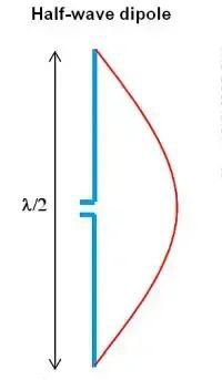
The simplest antenna is the dipole, with the half-wave dipole being the most popular. It has two elements, each a quarter wavelength long, with an impedance of 50 to 70 Ω at resonance, based on its length-to-diameter ratio. Its current flows in a sine wave pattern, creating a figure-eight radiation shape in the E-plane and a uniform pattern in the H-plane. An rf attenuator calculator is handy here to adjust signal levels and ensure accurate testing.
Older dipoles struggle when frequencies stray from their tuned point, as impedance depends on the length-to-wavelength ratio. Thin dipoles with high length-to-diameter ratios see bigger mismatches. Reducing this ratio cuts down on issues. An rf attenuation calculator can tweak signal strength to fix these mismatches.
Balanced dipoles connect to unbalanced coaxial cables via a balun (balanced-unbalanced transformer). Without it, currents on the cable’s outer layer cause interference or distort the radiation pattern. An rf signal attenuator calculator ensures clean signals in these setups.
Monopole Antennas: Simplicity and Efficiency
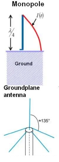
A monopole antenna replaces one dipole element with a conductive surface, keeping a quarter-wavelength length. Its current mimics a half-wave dipole, and its radiation pattern matches when placed on a conductive ground. Impedance drops to 30-40 Ω, half of a dipole’s. Height is vital here, and an antenna height calculator ensures the best setup.
The ground surface matters—radio stations bury radial wires around towers for stability. Ground plane antennas, a monopole type, use radial rods tilted at 135° to hit 50 Ω impedance for coaxial cables. An rf attenuator calculator fine-tunes signals in these systems.
Directional Antennas: Focused Power
Directional antennas boost power in specific directions by adding elements, enhancing gain, directivity, and beamwidth. A basic version uses two monopoles a quarter wavelength apart, fed with a 90° phase difference, creating a null to block interference. An antenna range calculator optimizes these features.
Yagi-Uda antennas, used for TV and VHF, have 4-30 elements and gains over 10 dB. An antenna range calculator measures their performance accurately.
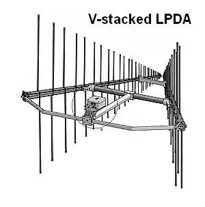
The LPDA, a directional type, uses parallel dipoles of increasing size and spacing, fed out-of-phase via a single line. Its active region shifts with frequency, offering broad bandwidth. Height and spacing are key, and an antenna height calculator ensures precision.
Its radiation pattern stays steady—120° in the H-plane, 60-80° in the E-plane. Stacking two LPDAs in a V-shape narrows the H-plane to 65°. An antenna range calculator tracks these patterns effectively.
Cutting-Edge Antenna Solutions
High-Frequency Antennas
For gigahertz frequencies, horn and waveguide antennas replace traditional designs. These need exact signal control, where an rf attenuator calculator ensures reliable measurements and performance.
Metamaterials: The Future of Antennas
Electromagnetic metamaterials are emerging for high frequencies, using structures like coils to interact with waves. Unlike typical antennas, they store and release energy. For microwave uses, their millimeter-scale features demand precision. An rf attenuator calculator helps manage signals in these innovative designs.

 Coaxial Cable Assembly
 Microwave Test Cable
 Coaxial RF Connector
 Coaxial RF Adapter
 Coaxial RF Termination
 Coaxial RF Test Probe
 Coaxial RF Attenuator
 RF Switch
 Coaxial RF Power Dividers