, .041 inch Pin, 50G")
, .041 inch Pin, 50G")
, .041 inch Pin, 50G")


 Coaxial Cable Assembly
 Microwave Test Cable
 Coaxial RF Connector
 Coaxial RF Adapter
 Coaxial RF Termination
 Coaxial RF Test Probe
 Coaxial RF Attenuator
 RF Switch
 Coaxial RF Power Dividers
$23.81
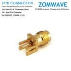
5 Days Ship Out. Negotiated Prcie. ZOMWAVE 2.4mm Female PCB End Launch Connector, .040 inch PCB Thickness (Max), .041 inch Pin Diameter connector has an interface type of end launch and a 50 Ohm impedance.2.4 mm female connector uses shield/contact solder as an attachment method. Our female 2.4 mm pcb connector provides a minimum frequency of DC and a maximum frequency of 50GHz. ZOMWAVE 2.4 mm female pcb connector has a PTFE dielectric type and a VSWR of 1.25. The ZOMWAVE 2.4mm Female PCB End Launch Connector, .040 inch PCB Thickness (Max), .041 inch Pin Diameter connector has a brass body with gold plating. Our 2.4 mm connector uses beryllium copper contact. This 2.4mm female pcb RF connector is RoHS and REACH compliant. Our 2.4 mm female connector is part of over 40,000 RF, microwave and millimeter wave components in stock for worldwide shipment. compatible only with the 2.4mm interface. Zomwave supplies 2.4 mm Female PCB End Launch Connector.
| Quantity | Price | Discount |
|---|---|---|
| 1-9 | $23.81 | 0% |
| 10-49 | $22.86 | 4% |
| 50-99 | $21.91 | 8% |
| 100+ | $20.00 | 16% |
200+ Call US
Get a lower discount price
| Configuration | |
| Connector Series | 2.4 mm |
| Connector Gender | Female |
| Connector Angle | Straight |
| Connector Mount Method | None |
| Attachment Method | Solder |
| Interface Type | End Launch |
| Material | |
| Centre Contact | Cube, gold plated |
| Body | Brass, gold plated |
| Insulators | PTFE |
| Electrical Specifications | |
| Impedance | 50 ohm |
| Frequency Range(From DC) | 50GHZ |
| VSWR | ≤1.25:1 (DC 0~50GHz) |
| Insertion Loss | 0.05 xSqt.(f_Ghz) |
| Voltage Rating | 150 V(rms) |
| Dielectric Withstanding Voltage | 500 V |
| Insulation Resistance | ≥500 Mohm |
| Mechanical Characteristics | |
| Mating Cycles | ≥ 500 cycles |
| Mating Torque | 5-7 in - lbs |
| Environmental Characteristics (RoHS Complliant) | |
| Temperature Rating | -40°C ~ +165°C |
| Corrosion (Salt Spray) | MIL-STD-202, Method 101, Condition B |
| Vibration | MIL-STD-202, Method 204, Condition D, 20 Gs |
| Shock | MIL-STD-202, Method 213, Condition I, 100 Gs |
| Thermal Shock | MIL-STD-202, Method 107. Cond. B, -40°C to +85°C |
| Moisture Resistance | MIL-STD-202, Method 106, Less Step 7B |
| Barometric Pressure (Altitude) | MIL-STD-202, Method 105, Condition C, 70k Ft |
Dimensions in mm/ [inch], Tolerance +1%


Q1. What is your delivery time?
A1). We promise within 5 days ship out for the standard products less than 200 pcs.
A2).Customized products would be 2~3 weeks lead time.
Q2. Which shipping way is available and how to track?
A1). By international Express like FedEx, DHL, TNT, UPS, normally door to door in 5~7 days.
A2). Tracking No. will be sent after goods ship out.
Q3. Do your price include freight cost and custom duty?
A1). Price do NOT include the freight cost and import duty.
A2). We can quote you the detail freight cost by our forwarder agent.
Q4. Which payment way is workable?
A1). We accept Wire Transfer (T/T) and PayPal payments (order value less than USD$500).
A2).Payment in advance for new clients.
Q5. What is the MoQ of your products?
A1). No MOQ request for standard products (include customized length cable) on our website.
A2). Other customized products we request 500 pcs MOQ (Minimum Order Quantity).
Q6. Could you supply the sample for me to test first?
A1). We are honored to offer you samples. New clients are expected to pay the sample fee.
A2). Sample fee can be refunded in your mass production order (total quantity up to 1000 pcs).
Coaxial Cable AssemblyMicrowave Test CableCoaxial RF ConnectorCoaxial RF AdapterCoaxial RF TerminationCoaxial RF Test ProbeCoaxial RF AttenuatorRF SwitchCoaxial RF Power DividersNo account yet?
Create an Account